
Operating
Remember While Reading
While reading this Operator's Manual, remember that:
PRE-OPERATION CHECK
· Apply parking brake and check if it operates properly.
· Check tire pressure and condition.
· Check wheels and bearings for wear and damage.
· Check location of controls and ensure they work properly.
· Verify steering operates freely.
· Activate throttle control lever several times to ensure it operates freely. It must return to idle position when released.
· Activate the brake levers and foot pedal to make sure the brakes fully apply. Levers and pedal must fully return when released.
· Ensure transmission lever is working then reset in PARK position.
· Check fuel, oil and coolant levels.
· Check for oil leaks on the engine/ transmission and drive train components.
· Ensure fuel valve is in fully open position (ON).
· Clean head lamps and taillight.
· Ensure front storage cover compartment is properly latched.
· Ensure seat is properly latched.
· If you transport cargo, respect load capacity. Ensure cargo is properly secured to the racks.
· If you are pulling a trailer or other equipment, ensure it respects the tongue capacity and towing capacity. Ensure trailer is properly secured to hitch.
· Look and feel for loose parts while engine is off. Check fasteners.
· Ensure the path of travel is free of persons and obstacles.
· Check operation of ignition switch, start button, engine stop switch, head lamps, dimmer switch, taillight and indicator lights.
· Start engine and drive forward slowly a few feet and apply all brakes individually to test them.
Correct any problem you may have found. See an authorized John Deere UATV dealer as necessary.
Avoid Damage to Plastic and Painted Surfaces
· Do not wipe plastic parts unless rinsed first.
· Insect repellent spray may damage plastic and painted surfaces. Do not spray insect repellent near machine.
· Be careful not to spill fuel on machine. Fuel may damage surface. Wipe up spilled fuel immediately.
CONTROLS/INSTRUMENTS/EQUIPMENT
NOTE: Some controls/instruments/equipment do not apply to some models. In these cases their reference numbers are deliberately missing in the illustrations. Some controls/instruments/equipment are optional on some models.


H - Speedometer/Indicator Lights
AA - Rear Cargo Box Gate (Buck EXT)
AB - Lateral Compartment (Buck EXT)
While reading this Operator's Manual, remember that:
NOTE: This section gives basic functions of the various controls of your UATV. For more details of how to operate one control in conjunction with others, refer to OPERATING INSTRUCTIONS further in this section.
Throttle Lever
Located on the right side of handlebar. When pushed, it increases the engine speed that allows the engagement of the transmission in the selected gear.
When released, the engine speed should return automatically to idle and the vehicle will gradually slow down.
Front Brake Lever
Located on the right side of handlebar. When compressed, the brake is applied. When released, it should automatically return to its original position. Braking effect is proportional to the force applied on the lever and to the type and condition of the terrain. The front brake will also have an effect on rear wheels through the drive train.
See the note at Rear Brake Lever below for additional information.
Rear Brake Lever
NOTE: Using the rear brake will have also an effect on front wheels because they are connected through the drive train. As on other wheeled vehicles. the vehicle weight is transferred to the front wheels when braking. To obtain greater stopping efficiency, the brake system distributes more braking force to the front wheels. This will affect vehicle handling and steering control when braking vigorously. Take it into account when braking.
Located on the left side of handlebar. When compressed, the brake is applied. When released, it should automatically return to its original position. Braking effect is proportional to the force applied on the lever and to the type and condition of the terrain. The rear brake will also have an effect on front wheels through the drive train.
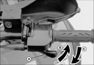
Brake Lever Lock
IMPORTANT: Avoid damage! Always use the park brake lever lock and engage the PARK position on the transmission lever when the vehicle is not in operation. |
Located on left side of handlebar on the rear brake lever. When applied, it prevents the vehicle from moving. Useful when the brake needs to be locked for example such as doing a K-turn, during transportation or when the vehicle is not in operation.
B - Press to apply parking brake
To engage mechanism: Squeeze brake lever and maintain while moving lever lock. Brake lever is now compressed and applying rear brakes.
To release mechanism: Squeeze brake lever. Lever lock should automatically return to its original position. Brake lever should return to rest position. Always release brake lever lock before riding. Using the foot brake will not release the brake lever lock.
Transmission Lever

Located on the left side of steering column. A 5-position lever (A): P, R, N, H and L.
To change the transmission position, completely stop vehicle then move lever to the desired position while pulling lever upward. Do not force lever. If unable to shift, gently apply throttle to move the vehicle and try again.
This position locks the transmission to help prevent vehicle movement. Always use when the vehicle is not in operation. In some circumstances, it may be necessary to rock the vehicle back and forth to move the gears in the transmission to allow the park to be engaged.
Before moving vehicle in reverse, ensure the path behind is clear of obstacles or bystanders. Remain seated. |
This allows the vehicle to go backward. The vehicle reverse speed is limited to 15 km/h (9 mph).
This position disengages the transmission to allow manual vehicle movement or towing.
This selects the high speed range of the transmission in the gear box. It is the normal riding position. It allows the vehicle to reach its maximum speed.
IMPORTANT: Avoid damage! Use the low speed range to pull or push any load or to climb a steep slope. |
This selects the low speed range of transmission in the gear box. It is the working position. It allows the vehicle to move slowly with the maximum traction and power.
Multi-Function Switch

The multi-function switch (A) is located on the left side of handlebar.
Electric Gear Shift Button

Located at the middle of multi-function switch. When pressing on the upper face (B), it shifts the transmission to the next higher gear. When pressing on the lower face (C), it shifts the transmission to the next lower gear.
The lower the gear, the slower the vehicle speed and the higher the gear, the higher the vehicle speed.
Vehicle must be running to allow gear change.
The button must be released then pressed again to perform another gear shift.
There are 5 gears in high and low gear positions.
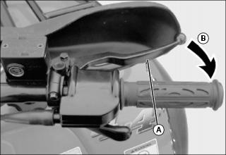
Manual/Autoshift Selector (Except Buck EXT)

Located beside head lamp dimmer switch, at the bottom of the multi-function switch. It is possible to change the mode at any time, even when vehicle is running
The autoshift mode (A) activates a change of gear in accordance with the engine RPM and throttle opening. When autoshift mode is selected, just press or release throttle lever.
On some occasions, it may be useful or necessary to manually change the gear selection (B). The electronic module will allow the rider to override the autoshift mode by pressing the shift button to a lower gear or a higher gear. The autoshift mode will be kept and the shifting sequence will resume after shift is performed.
While in autoshift mode and Low gear range, the machine will never downshift from 2 to 1.
However, if the vehicle is used in severe conditions, it is highly recommended to use the manual mode (use the gear shift button).
Start/Stop Switch
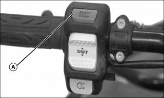
Located on top of the multi-function switch. Dual function switch (A).
To start engine, press and hold the switch. Release immediately after engine is started.
To stop engine, fully release throttle lever then press the switch. It is not necessary to hold the switch.
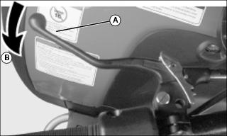
Head Lamp Dimmer Switch
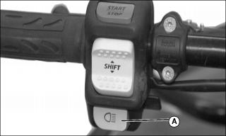
Located under the electric gear shift button. Toggle type switch. It allows selection of head lamp intensity.
Indicator Lights Cluster
NOTE: When first turning switch to ON (either position), all indicator lights will turn on for a brief moment. This validates their operation. Thereafter, only the lights that are activated will remain on.
Temperature lights stay on until the engine runs.
If all lights flash, it indicates a particular malfunction of the transmission or the electrical system. See an authorized John Deere UATV dealer as soon as possible.
Gear Position Display

Gear Selection Display (A) located left of cluster. It lights up to indicate the gear selection whenever the ignition switch is turned on when the transmission lever is not in PARK or in NEUTRAL position (whether or not engine is running).
If all gear lights flash while shifting gear, it indicates the shifting is not completed yet. Simply wait until the shifting completes or retry the shift with the gear shift button.
If all gear lights flash continuously, it indicates a damaged sensor (gearbox). Although the vehicle can still be operated in this condition, downshifting may increase engine "braking". Drive slowly. See an authorized John Deere UATV dealer as soon as possible.
· Located on right side of cluster. They light up to monitor different functions.
Buck Series

If PARK, REVERSE or NEUTRAL lights flash continuously, it indicates a damaged sensor (sub-transmission). Although the vehicle can still be operated in this condition, downshifting may increase engine "braking". Drive slowly. See an authorized John Deere UATV dealer as soon as possible.
IF AUTOSHIFT light flashes, it indicates a possible problem with the TPS sensor. The manual mode is immediately selected. See an authorized John Deere UATV dealer as soon as possible.
Indicator Lights Description
When lit, it indicates the transmission is in park position.
When lit, it indicates the transmission is engaged in reverse.
When lit, it indicates the transmission is in neutral position.
When lit, it indicates the vehicle is operating in autoshift mode.
Only lit in the bulb check, otherwise it is not used.
When this indicator light is on, it indicates the oil pressure is low.
When this indicator light is flashing, it indicates overheating of the engine.
When the indicator light is on, it indicates high intensity is selected on the headlights.
Speedometer

B - Odometer/Trip Meter/Hour Meter
These vehicles are equipped with an electronic speedometer. It indicates the speed of the vehicle either in MPH and km/h.
The speedometer is located at the middle of cluster and it is backlit when the ignition switch is turned ON (either position).
Odometer/Trip Meter/Hour Meter
Display Selection Button
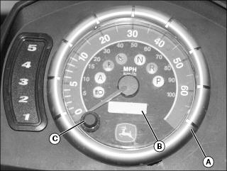
B - Odometer/Trip Meter/Hour Meter
The odometer always appears when turning the ignition switch ON (either ON position). To change the display to the trip meter, depress the display selector button.
Depressing display selector button again will change display for the hour meter. Push display selector button again to return to odometer.
Odometer
Odometer records the total distance travelled in miles or kilometers.
The odometer is factory pre-set in miles, but it is possible to change it's reading to kilometers. See your John Deere dealer to change the speedometer.
Trip Meter
The trip meter records distance traveled since it has been reset. Distance traveled is displayed in either miles or kilometers.
It can be used to establish a fuel tank range or distance between two-way points for instance.
Push and hold display selector button for two seconds to reset the trip meter, in any mode.
Hour Meter
NOTE: The hour meter is a 5 digit display and will read hours up to 99H59M and after that the hour meter will read only hours and not minutes, up to 9999H.
The hour meter records time in hours and minutes but will drop the minutes after 99 hours and 59 minutes.
Ignition Switch
NOTE: While engine can be stopped by turning ignition key off, we recommend the engine be stopped by pressing the start/stop switch. Remember to turn key to off to avoid unnecessary battery discharge.

Key-operated, 3-position switch (A): off, on with lights and on without lights.
Insert key in switch and turn to the desired position. To remove key, turn key to off then pull it out.
NOTE: The headlights automatically dim to low intensity when ignition key is switched to on.
The on with lights position, turns on all lights with either the engine running or not. The headlights automatically dim to low intensity. Remember that having the lights on without the engine running discharges the battery. Always turn ignition to off after engine has been stopped.
Auto Shut-Down
If for some reason, the engine is not started within approximately 6 minutes, the MPEM (Multi-Purpose Electronic Module) will shut down to cut all electrical system functions. Simply turn the key to off then to on to regain normal use.
Choke Knob Lever
Located at bottom of cluster. This device features a variable lever to ease cold start.

Picture Note: Choke Knob Lever in OFF Position
Position OFF is for normal use with a warm engine (pushed in).

Picture Note: Choke Knob Lever in the Full Choke Position
The full choke position is used for lower temperature (fully extended).
The other positions between OFF and FULL position, will be use depending on the temperature.
To adjust the choke lever resistance, lift the rubber bellows then screw the choke lever nut. Do not torque excessively because the choke lever won't move easily. Put back the rubber bellows in its original position.
Fuel Tank Cap

Unscrew counterclockwise and remove cap (A) to allow fuel tank filling then fully tighten clockwise.
Fuel Gauge

Located under cluster, the gauge shows an approximate amount of the fuel in tank.
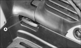
Fuel Valve
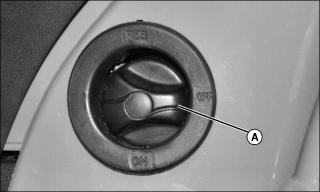
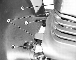
Fuel valve (A) located on left side panel under front part of seat. This is a 3-position rotary valve: OFF, ON, RES. Rotate the knob to align its pointer with ON, OFF or RES.
Align this pointer toward the desired position.
OFF
Stops fuel supply to carburetor.
ON
Allows fuel to flow to carburetor. This is the normal position for operation of the vehicle. For best performance, be sure fuel valve is always fully open.
RES (Reserve)
When fuel is exhausted in the fuel tank when in the ON position, an emergency supply of fuel is available by turning the knob to RES. The reserve contains approximately 30% of the fuel tank capacity. Use this position only when the ON supply is empty.
When down to the reserve, refuel as soon as possible. Be sure to turn the valve back to the ON position after refuelling.
Rear Brake Pedal
NOTE: The brake will have also an effect on front wheels through the drive train.
Located on the right footrest. When pressed down, the rear brake is applied. When released, it should return to its original position. Braking effect is proportional to the force applied on the pedal and to the type and condition of the terrain.
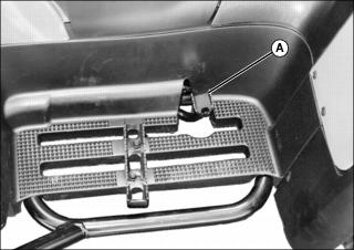
Rewind Starter Handle
The rewind starter handle (A) is provided as an emergency starting device.
Follow the usual starting procedure; but use the rewind starter instead of the electric starter.
Located on left side panel under front part of seat. Auto-rewind type. To engage mechanism, pull handle slowly until a resistance is felt then continue to slowly pull the handle until the compression stroke peak (strong rotating resistance) is passed, then pull vigorously. Slowly release handle.
Footpeg

Located on footrest. Use the footpeg (A) to keep your feet stable.
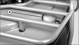
Storage Compartment

Storage compartment located in front of vehicle. Convenient location to carry personal articles such as an a Operator's Manual, helmet, spare spark plugs, first aid kit, etc. Unlatch cover (A), gently lift then pull to front of vehicle to remove cover.
The compartment is equipped with a drain plug under the tool box (B). Remove plug to allow draining when necessary. Reinstall plug when finished.
Tool Box
The tool box is located in the storage compartment. It contains tools for basic maintenance, this Operator's Manual.
The tools included in the tool box are:
Seat Latch
Located underneath rear end of seat. It allows the removal of seat to give access to engine compartment.
Seat Removal
· Pull latch upward while gently lifting rear of seat. Continue lifting movement until you can release the front retaining devices then completely remove seat.
· Push latch backwards while gently lifting rear of seat. Continue lifting movement until you can release the front retaining devices then completely remove seat.
Seat Installation
· Place seat (C) to allow the insertion of the U-shaped bracket (A) over the rollers (B). Gently slide the brackets over rollers then lower seat. When seat rests in its position, firmly push seat down to latch.
Front/Rear Cargo Racks
Located on top of chassis at front and rear. Convenient racks to carry gear.
Refer to SPECIFICATIONS for carrying loads and cargo weight distribution recommendations.
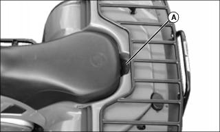
Air Duct
Buck Series except Buck EXT
Located on rear fenders. They force the flow of air to cool radiator and supply air inside air box.
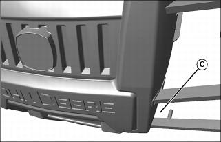
Trailer Hitch
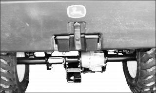
NOTE: A pin with a wave pin are provided at front and at rear of vehicle to install the hitch properly.
Transferable hitch provided with EX models. Can be installed at rear (below rear axle) as well as at front of UATV. Convenient to install a ball to tow a trailer or other equipment. Install the proper ball size as per trailer manufacturer recommendations. Refer to SPECIFICATIONS for carrying loads and towing recommendations.

When installing hitch in the front of the UATV, use hole (A). When installing hitch in the rear of the UATV, use hole (B).
Follow manufacturer instructions for proper attachment.
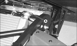
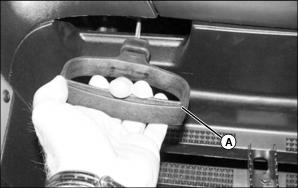
Radiator Cap
Buck Series except Buck EXT
Located at rear of rear panel. It provides access to the radiator filling neck.
Pull the protector cap (A) to give access to the radiator cap. When finished, properly reinstall radiator cap then protector cap.
Buck EXT
Lift rear cargo box to gain access to the radiator cap. Then, properly reinstall radiator cap and close the rear cargo box properly.
12-Volt Power Outlet
It is located beside ignition key on cluster.
Convenient for handheld spotlight or other portable equipment.
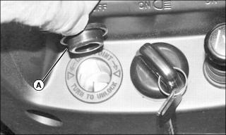
Remove cap (A) to use. Always reinstall protective cap after use to protect against weather.
Do not exceed the rating capacity. See SPECIFICATIONS
An auxiliary supply is available to connect additional accessories. Two connectors are available in the wiring harness at the rear of vehicle. See an authorized John Deere UATV dealer for more details.
Fuses
The electrical system is protected with fuses. Refer to MAINTENANCE for details.
Winch (If Equipped)
Buck EX only
Located behind front skid plate.
Winch Control Switch
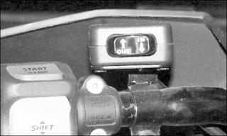
Located on the left side of the handlebar.
To take out wire rope from winch, press the left side of switch
To get wire rope into the winch, press the right side of switch.
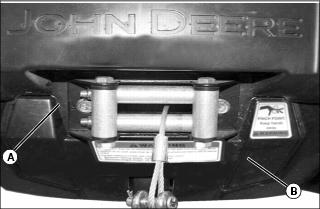
Fairlead
Located on the front skid plate (A).
The roller fairlead (B) is used to prevent the damages to the vehicle and guide the wire rope into the winch.
Winch Pulling Power
Never winch with fewer than five wraps of cable around winch drum. Cable could break free from drum causing dangerous backlash. |
The greatest pulling power of the winch is available at the first layer of cable around the drum, decreasing with each successive layer. Do not operate winch with fewer than five wraps of cable around the drum.
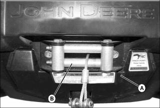
Using the Hook Strap
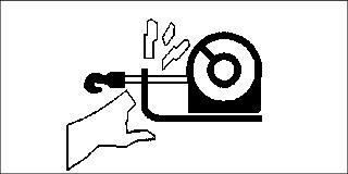
Hands and fingers can become caught and crushed in moving parts of winch. Keep hands away from wire rope, hook, and fairlead opening. Always use hook strap when spooling. |
Keep nylon hook strap (A) in a secure and convenient location on your vehicle. The hook strap must be used at all times when spooling to prevent hands from coming in contact with the wire rope, hook, and fairlead opening (B) during operation.
Place loop end of strap around winch hook. Hold other end of strap in hand when spooling.
Spooling Out
Winch line can be spooled off the drum by using the mounted control or by manually free spooling. Free spooling prevents battery drain and is the quickest way to remove large lengths of cable.
1. Park machine safely. (See Parking Safely in the SAFETY section.)
2. Use the winch control switch to power out enough winch cable to remove any tension on the line.
3. Disengage clutch to the FREESPOOL position.
4. Attach hook strap to hook. Grasp hook strap and manually spool out enough cable for rigging.
3. Place transmission in park.
4. Leave engine run to avoid draining battery.
5. Use mounted control to spool out winch line. Make sure cable does not wrap over itself on the drum.
Spooling In
3. Place transmission in park.
4. Leave engine run to avoid draining battery.
5. Stand as far from winch as the control switch will allow.
NOTE: Stop winching if cable becomes stacked on one end of drum due to side pull operation. Correct situation by spooling out uneven section of line and repositioning it to opposite end of drum to provide space for continued winching.
6. Spool in the winch line evenly and tightly on the drum in a clockwise direction as viewed from motor end of winch.
3. Place transmission in park.
5. Leave engine run to avoid draining battery.
6. Stand as far from winch as the control switch will allow.
7. Have an assistant hold the hook strap and maintain as much tension as possible on winch line.
8. Power in the winch line evenly and tightly on the drum in a clockwise direction as viewed from motor end of winch. Assistant should walk toward winch while maintaining tension.

9. Stop winching when hook is a minimum of 1.2 m (4 ft) from roller fairlead (A).
11. Operate winch control switch intermittently until slack is removed from winch line. Do not overtighten.
12. Store hook strap in a secure location.
3. Place transmission in park.
5. Leave engine run to avoid draining battery.
6. Make sure existing cable on drum is evenly and tightly layered.
7. Arrange winch line so it will not kink or tangle when spooled.
8. Stand as far from winch as the control switch will allow.
9. Spool in enough cable to complete next full layer on drum.
10. Repeat process until hook is a minimum of 1.2 m (4 ft) from roller fairlead (A).
12. Operate winch control switch intermittently until slack is removed from winch line. Do not overtighten.
13. Store hook strap in a secure location.
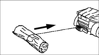
Selecting an Anchor Point
Select an anchor point as far away as practical and strong enough to withstand the load. Spooling out as much cable as possible provides the winch with its greatest pulling power and minimizes cable damage caused by top layers mashing down into bottom layers during short pulls.
Another vehicle may be used as the anchor point, but natural anchors such as trees, stumps, and rocks are often most convenient. If natural anchors are not available, objects such as a spare tire or log can be partially buried to serve as a suitable anchor point.
If several anchors are available but not strong enough individually, it may be possible to attach a chain or strap around the group of anchors to form a strong collective anchor point.
Using Vehicle as the Anchor Point
1. Stop vehicle so it is lined up as straight as possible with the load.
2. Park machine safely. (See Parking Safely in the SAFETY section.)
5. Place transmission in park.
6. Make sure park brake is locked.
7. Leave engine run to avoid draining battery.
8. Proceed with winching operation.
Preparing Vehicle for Self-Recovery

1. Select a suitable anchor point.
2. Clear debris from path of vehicle movement and around the tires and frame.
5. Place transmission in neutral.
7. Leave engine run to avoid draining battery.
8. Proceed with winching operation.
Preparing the Rigging
Single and double line rigging are common techniques. Most single line pulls are made with a straight cable connection to an anchor point. Double line rigging involves use of a pulley block. Double line pulls will reduce the load on the winch to half with little affect on spooling speed. Double line rigging is useful for moving very heavy loads as it doubles the power of your winch.
Keep in mind the greatest pulling power of the winch is provided on the first layer of the drum. Therefore, always attempt to rig your pulls with as much cable spooled out as possible. Never, under any circumstances, winch with less than five wraps of cable around the drum or the cable could break loose and cause serious injury.
Try to align pulls as straight as possible to prevent uneven wrapping of the winch line. Too much cable on one end of the drum will damage the winch or cable.
Take the time to properly prepare the rigging for safe and effective operation.
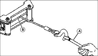
Single Line Pull For Vehicle Recovery:
1. Secure chain (A) around anchor point (B).
2. Spool out winch cable and attach to chain.
Single Line Pull For Moving Loads:
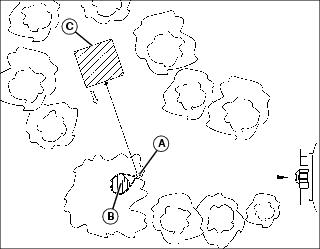
1. Secure pulley block (A) to anchor point (B).
2. Secure chain around load (C).
3. Spool out winch cable and route through pulley block.
4. Attach winch cable to chain.
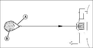
Double Line Pull For Vehicle Recovery or Moving Loads
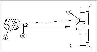
Picture Note: Vehicle Recovery

1. Secure pulley block (A) to anchor point/load (B).
2. Spool out winch cable and route through pulley block.
IMPORTANT: Avoid damage! The winch line hook must be secured at the vehicle frame when double line rigging. Never attach the hook to the rack, bumper, or any other part. |
3. Attach the winch line hook at the side of the vehicle frame (C) that ensures the straightest line pull.
IMPORTANT: Avoid damage! Indirect double line pulls are not recommended unless absolutely necessary. Winch pulling power and line speed decreases as angle between winch cables increases. |

Indirect double line pull used to bypass obstacles or impassable terrain:
1. Secure pulley block (A) to load (B).
2. Secure chain around anchor point (C).
3. Spool out winch cable and route through pulley block.
4. Attach winch cable to chain.
Rear Cargo Box (EXT only)
Located at the rear of vehicle. The rear cargo box is designed to receive various materials.
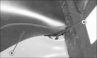
Release Lever
Release lever (A) located under rear cargo box on the right side of seat.
It allows the dumping of rear cargo box.
To dump rear cargo box, move release lever toward the right side.
Rear Cargo Box Gate
Located at the rear end of the rear cargo box.
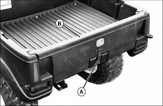
To open gate, unlatch (A) and lift up gate (B) about 50 mm (2 in.) then slowly pivot gate downwards, toward rear. Two cables located on each side of rear cargo box will hold gate in place.
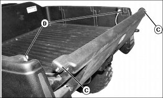
To close gate, raise and lift up gate. Then insert gate locks (C) into lock grooves (D). Install latch.
Lateral Compartment

Lateral compartments (A) located on both sides of vehicle. The compartments are equipped with a drain plug. Remove plug to allow draining when necessary. Reinstall plug when finished.
Dumping the Rear Cargo Box
Move the release lever toward right side and lift the front end of the rear cargo box to dump.
Cargo
NOTE: Includes driver and all other loads and added accessories.
Buck Series Load Allowances
Total load allowed 220 kg (485 lb)
Rear Rack and tongue Load 80 kg (175 lb)
Front rack and storage 40 kg (90 lb)
Buck EXT Series Load Allowances
Total load allowed 364 kg (800 lb)
Front rack and storage 40 kg (90 lb)
Rear cargo box and tongue load 273 kg (600 lb)
Lateral compartments (both) 14 kg (30 lb)
Secure Material in Rear Cargo Box
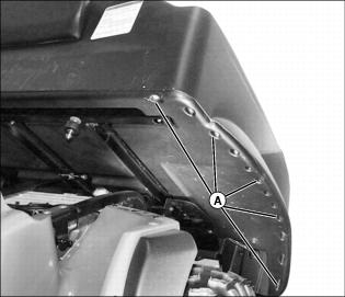
When carrying material in rear cargo box, it is highly recommended to secure the material properly. See the illustration for the tiedown locations.
UATV Flag (Optional)
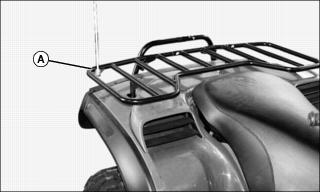
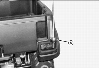
Use the appropriate mounting location (A) when installing an optional UATV Flag.
Starting Instructions
· Transmission lever must be on PARK or NEUTRAL to allow engine starting.
· For your convenience, an override mode allows for starting the engine with the transmission lever in any position. Press and hold the front or rear brake lever or the brake pedal while pressing the start button.
General
· The engine can be started in any gear (from 1 to 5).
· To start engine, insert key in ignition switch and turn to on then press the start/stop switch.
Initial Cold Starting
· Insert key in ignition switch and turn to on.
NOTE: On Buck series, when the temperature is below - 15°C (5°F), the primer kit installation is recommended. See an authorized John Deere UATV dealer.
Picture Note: Choke Knob Lever in the Full Choke Position
· In cold weather, colder than 0°C (32°F), place the choke lever in full position.
NOTE: The throttle can be used to help start the engine. Press the throttle lever slightly. If it is pressed too much, the choke system will not be activated.
· Press the start/stop switch and hold until engine starts.
· Release start/stop switch immediately when engine has started.
IMPORTANT: Avoid damage! Increased idle speed caused by choke will make shifting difficult. Always warm up machine with choke, then turn choke off before operating. |
NOTE: Over using choke may flood engine and make it hard to start. Refer to SPECIAL PROCEDURES if this occurs.
· After a few seconds, move the choke lever from full choke position to an intermediate position until a best engine RPM is achieved.
· When the engine is warm, push the choke lever to OFF and release brakes.
Warm Engine Starting
· Start the engine as explained above but without the choke. If the engine will not start after two 5-second attempts with the electric starter, place the choke lever between the FULL and the OFF position. Start the engine without activating the throttle lever. After few times, push the choke lever to OFF.
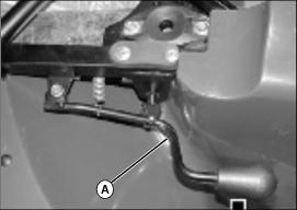
Emergency Manual Starting
· Manual start is provided in the event electric start does not work.
· If the engine indicator light is turned off, it indicates the electrical system is in the auto shut-down mode. Turn the ignition key off then on to reactivate it.
· Follow the same procedure as starting procedures above except use the rewind starter to start instead.
· Grasp manual starter handle (A) firmly and, slowly, crank engine until a resistance appears.
· Pass this resistance and release the handle.
· Take again the handle firmly and crank engine.
· Repeat this procedure completely if necessary.
Stopping Engine
Children or bystanders may attempt to move or operate an unattended machine. Always lock the park brake and remove the key before leaving the machine unattended. |
Release throttle and completely stop the vehicle.
Apply parking brake by using brake lever lock on rear brake lever.
Set transmission lever in PARK position.
Press the start/stop switch or push the engine stop switch in off position.
Turn key in ignition switch to off.
Remove key from ignition switch.
Shifting Transmission
NOTE: The brake must be applied when the transmission lever is engaged in the park position.
Apply brakes and select the desired gear range H/L or R.
Gradually press the throttle lever to increase engine speed and thus engaging the centrifugal clutch.
NOTE: While any throttle position can be used during shifting, it is recommended to slightly release the throttle position during upshifting.
When vehicle speeds increases, slightly release throttle lever while pressing the electronic gear shift button to upshift one gear then release button and press throttle lever again to continue the acceleration. Repeat until the last gear if desired or until vehicle speed you want is attained.
Reverse the sequence to downshift.
Manual/Auto shifting Selector (Except Buck EXT)
When selector is in autoshift mode, the transmission upshifts automatically when the vehicle speed increases. Inversely, when vehicle speed decreases, the transmission downshifts automatically, except for low range, the transmission will never automatically downshift from 2 to 1.
Using Reverse
· The same procedures as Shifting The Transmission above apply except for the following.
· Set the transmission lever in REVERSE position.
· Speed is limited in reverse.
Special Procedures
Flooded Engine
· When the engine does not start after several attempts, the engine may be fuel flooded. Proceed as follows.
· Turn ignition switch to on and ensure choke is not applied.
· Fully press throttle lever and hold while starting the engine.
· As soon as the engine starts, release throttle lever. Do not race engine.
· Disconnect the ignition coil or unplug the spark plug cables.
· Clean the ignition coil and the spark plugs area then remove spark plugs (tools are supplied in tool box).
· Crank engine several times. Add a small quantity of engine oil in cylinder (equivalent to a cap of oil quart bottle). Install new spark plug(s) if possible or clean and dry spark plug(s).
· Start engine. If engine continues to flood, see an authorized John Deere UATV dealer.
Engine Overheat
· If engine overheats and indicator light turns on, try the following:
· Ensure air ducts are not obstructed.
· Check and clean radiator fins. See MAINTENANCE section.
· Reduce vehicle speed but try to keep vehicle moving to supply air to radiator. If engine is still overheating after approximately one minute, stop vehicle and set transmission to PARK. Stop engine.
· Place the ignition switch to on position (do not restart engine yet). The radiator fan will cool the radiator.
· Let engine cool down. Check coolant level and refill if possible
· See an authorized John Deere UATV dealer as soon as possible.
Turn Over
When vehicle is turned over or stays tilted on the side, place the vehicle in its normal operating position (on all four wheels) and wait 3 to 5 minutes before starting engine. Before starting engine, check engine oil level and refill if necessary. If the oil pressure light stays on after starting engine, stop engine and see an authorized John Deere UATV dealer as soon as possible.
UATV Immersion
Should the UATV become immersed, it will be necessary to take it to an authorized John Deere UATV dealer as soon as possible. Don't start the engine! Immersion of the UATV can cause serious damage if the correct restart procedure is not followed.
Post-Operation Care
When vehicle is used in salt-water environment (beach area, launching/loading boats etc.), rinsing the vehicle with fresh water is necessary to preserve vehicle and its components.
Metallic parts lubrication is highly recommended. Use John Deere LUBE. This must be performed at the end of each operating day.
When vehicle is operated in muddy conditions, rinsing the vehicle is recommended to preserve vehicle and its components and to keep lights clean.
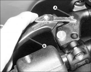
Emergency Shifter
If the shifting system is not operational, you may use the emergency shifter. It allows transmission gear change when the vehicle is not in motion. You set the desired gear, the transmission remains in this gear. No gear change can take place since the shifting system is not operational. The shifter shaft end is located on rear side of engine.
Place transmission in PARK position.

A - Unfold tab as a right angle (90°).
B - Insert the screwdriver here as a handgrip.
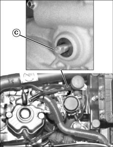
Use the special tool in the tool box to rotate the emergency shifter (C). Unfold the tool approximately at a right angle (90°). Insert the screwdriver included in the tool box at the end of the special tool so that it can be used as a handgrip.
Insert the tool to the end of the shifter shaft (C).
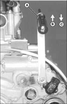
A - Use screwdriver as a handgrip
NOTE: The 2nd or 3rd gear is recommended.
Pull special tool upward to downshift and push downward to upshift. Place the gear in the desired position.
Remove the special tool. Fold the tool. Replace tool and screwdriver in tool box.
Storage and Preseason Preparation
NOTE: Have an authorized John Deere UATV dealer inspect fuel system integrity as specified in Maintenance Chart.
When a vehicle is not in use for more than one month, proper storage is a necessity.
See an authorized John Deere UATV dealer for proper procedures.
When using your UATV after storage, a preparation is required. See an authorized John Deere UATV dealer for proper procedures.
Storing Safety
Preparing Machine for Storage
1. Repair any worn or damaged parts. Replace parts if necessary. Tighten loose hardware.
2. Repair scratched or chipped metal surfaces to prevent rust.
3. Remove grass and debris from machine.
4. Wash the machine and apply wax to metal and plastic surfaces.
5. Run machine for five minutes to dry belts and pulleys.
6. Apply light coat of engine oil to pivot and wear points to prevent rust.
Preparing Fuel and Engine For Storage
Fuel:
1. Park machine safely in a well-ventilated area. (See Parking Safely in the SAFETY section.)
NOTE: Try to anticipate the last time the machine will be used for the season so very little fuel is left in the fuel tank.
2. Turn on engine and allow to run until it runs out of fuel.
4. Mix fresh fuel and fuel stabilizer in separate container. Follow stabilizer instructions for mixing.
NOTE: Filling the fuel tank reduces the amount of air in the fuel tank and helps reduce deterioration of fuel.
5. Fill fuel tank with stabilized fuel.
6. Run engine for a few minutes to allow fuel mixture to circulate through carburetor.
Engine:
Engine storage procedure should be used when vehicle is not to be used for longer than 60 days.
1. Change engine oil and filter while engine is warm.
2. Service air filter if necessary.
3. Clean debris from engine air intake screen.
· Remove spark plugs. Put 30 mL (1 oz.) of clean engine oil in cylinders.
· Install spark plugs, but do not connect spark plug wires.
· Crank the engine five or six times to allow oil to be distributed.
5. Clean the engine and engine compartment.
7. Clean the battery and battery posts. Check the electrolyte level, if your battery is not maintenance free.
8. Close fuel shut-off valve, if your machine is equipped.
9. Store the battery in a cool, dry place where it will not freeze.
NOTE: The stored battery should be recharged every 90 days.
IMPORTANT: Avoid damage! Prolonged exposure to sunlight could damage the hood surface. Store machine inside or use a cover if stored outside. |
11. Store the vehicle in a dry, protected place. If vehicle is stored outside, put a waterproof cover over it.
Removing Machine From Storage
3. Check battery electrolyte level, if your battery is not maintenance free. Charge battery if necessary.
5. On gas engines: Check spark plug gap. Install and tighten plugs to specified torque.
6. Lubricate all grease points.
7. Open fuel shut-off valve, if your machine is equipped.
8. Run the engine 5 minutes to allow oil to be distributed throughout engine.
9. Be sure all shields and guards or deflectors are in place.
Transportation
When transporting a vehicle, secure vehicle to trailer or in pickup box with suitable tie-downs. Using ordinary ropes is not recommended
Place the fuel valve to OFF position.
Select the park position and set the parking brake.
Secure the vehicle to front by the front bumper and rear by the frame.