Installing
Install Machine Weights and Chains
NOTE: Before attaching snowblower, remove mower deck from machine.
Two 19 kg (42 lb.) rear suitcase weights with weight bracket are required for stability. Rear tire chains are recommended for traction (check your machine operator's manual for tire size). See your Authorized Service Center for tire chain, weight, and weight bracket part numbers.
Connect Clutch Cable (Mechanical PTO Tractors Only)
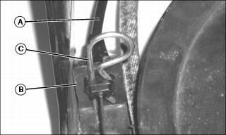
1. Push clutch cable (A) through clutch cable bracket (B). Secure with original 1/8 in. spring locking pin (C).
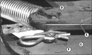
2. Attach clutch cable spring (D) to idler bracket (E) using 3/8 in. washer (F) and.08X1.58 spring locking pin (G).
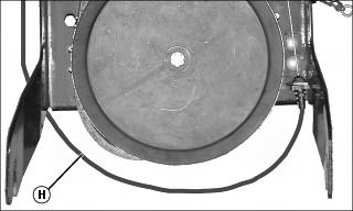
3. Mechanical PTO tractor only: Route clutch cable (H) around left side of clutch frame, beneath large sheave.
Attach Clutch Idler Assembly to Tractor
Keep hands and feet out from under attachment when removing or installing. |
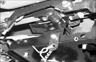
1. Slide rear slots of clutch idler assembly (A) onto tractor rockshaft inside of tractor frame.
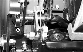
2. Raise front of clutch idler assembly until spring hooks (B) latch over tractor brake shaft (C).
Install Upper V-Belt
IMPORTANT: Avoid damage! Route upper V-belt inside idler. Routing belt incorrectly can cause belt damage. |
· Mechanical PTO tractors: Pull back on PTO lever.
· Electric PTO tractors: Push down on PTO switch.
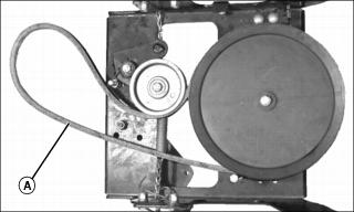
Picture Note: Top view (idler assembly removed for clarity).
2. Route upper V-belt (A) around pulley and tensioner as shown.
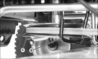
3. Route upper V-belt through belt guides (B) and around tractor pulley (C) as shown.
Mount Snowblower to Machine
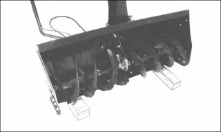
NOTE: To aid in installation, the snowblower should be blocked approximately 82 mm (3 1/4 in.) off the ground.
1. Block up each end of snowblower with two pieces of wood as shown.
2. Move lift handle forward to lowered position.
4. Put transmission in N (neutral).
NOTE: Tractor and snowblower should be closely aligned; otherwise, the snowblower frame can bind between the mounting brackets and muffler shield.
5. Align front of tractor with snowblower frame.
6. Automatic models only: Pull out free-wheeling lever at rear of tractor.
7. Move the snowblower lift handle forward to lowered position. Lift up on handle to tilt the snowblower frame upward. Have a helper slowly push the tractor forward toward the snowblower, or use your left foot on the front tire to roll the tractor forward.
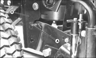
8. Guide the snowblower frame between the tractor mounting brackets and muffler heat shield. The mounting pins (A) of the snowblower frame should slide into the slots in the mounting brackets (B). It may be necessary to pull back on the lift handle to assist the pins in seating into slots if they bind.
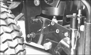
9. Install the clevis pin on the left side of the machine:
· Push down on the chute rotation support tube, this will pivot the snowblower forward to allow the holes in the snowblower and mounting bracket to align.
· Install the 5/8X1-1/4 in. clevis pin (C) and secure with 1/8 in. spring locking pin (D).
10. Install the clevis pin on the right side of the machine:
· Move the snowblower lift handle to the raised position. Push down on the snowblower lift handle to pivot the right side of the machine forward to align the lower pin holes.
· Install the 5/8X1-1/4 in. clevis pin (C) and secure with 1/8 in. spring locking pin (D).
11. Automatic models only: Push in free-wheeling lever at rear of tractor.
Install Lower V-Belt
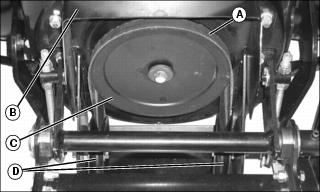
1. Check routing of lower V-belt (A) in snowblower assembly (B). Ensure that V-belt passes over top of auger pulley (C) and then twists 1/4 turn to pass under each side idler pulley (D).
2. Lower snowblower to ground.
3. Route lower V-belt (E) around pulley and tensioners as shown.
4. Pull chain until spring protrudes from hole and secure spring with 1/8 in. spring locking pin (F).
5. Hang pull chain handle (G) on J-pin.
Set Tension In Upper V-Belt
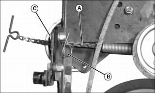
Electric PTO machine only: Pull chain (A) until spring locking pin (B) hits inside of clutch idler assembly frame. Install 1/8 in. spring locking pin (C) on outside of clutch idler assembly frame.
Lubricate Snow Blower
Lubricate idler, snow blower assembly, auger and discharge chute as described in Service section.
