
Assembly
Identify Parts
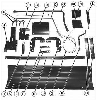
Bag of Parts
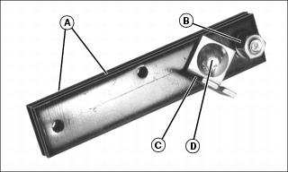
Attach Parts to Blade
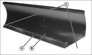
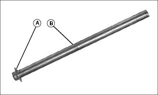
1. Attach scraper plate (A) to front of blade (B) using two 5/16X3/4 in. carriage bolts and 5/16 in. lock nuts (C).
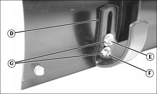
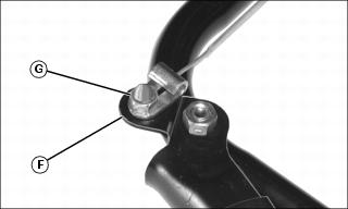
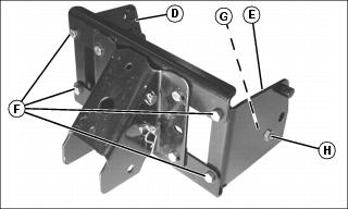
2. Attach two skid shoes (D) to rear of blade using four 5/16X1 in. carriage bolts (F), four 5/16 in. washers and four 5/16 in. lock nuts w/nylon insert (G).
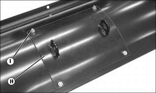
3. Attach reinforcement plate (H) to rear of blade using four 5/16X3/4 in. carriage bolts and 5/16 in. lock nuts w/nylon insert (I).
Install Angle Lock Bars
1. Align holes and join two angle lock bars (A) together using 3/8X1-1/4 in. carriage bolt and 3/8 in. lock washer and 3/8 in. nut (B). Do not tighten.
2. Install cable mount bracket (C) as shown using 3/8X1-1/4 in. carriage bolt and 3/8 in. lock washer and 3/8 in. nut (D).
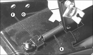
4. Insert round hook end of extension spring (E) through hole in spring mount bracket (F) on push channel assembly.
5. Insert straight hook end of angle lock spring through hole in angle lock bars (G) as shown.
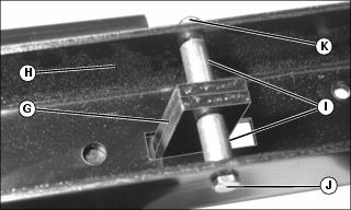
6. Insert angle lock bars (G) through push channel assembly (H). Place one .28 IDX.95 in. spacer (I) between each side of angle lock bars and push channel assembly. Install 1/4X3-1/4 in. hex bolt (J) through push channel assembly, spacers and lock bars. Secure with 1/4 in. lock nut w/nylon insert (K).
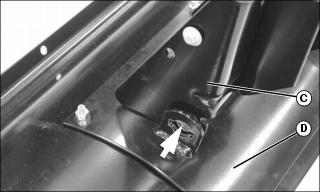
Attach Control Cable to Cable Mount Bracket
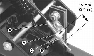
1. Install 5/16 in. jam nut (A) onto threaded end of control cable (B) so that 19 mm (3/4 in.) of threads are exposed.
2. Insert control cable into cable mount bracket (C).
3. Install 5/16 in. jam nut (D).
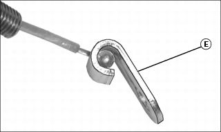
4. Insert ball end of control cable through clevis lanyard fitting (E).
IMPORTANT: Avoid damage! Align clevis lanyard fitting with cable mount bracket. Misalignment may cause binding of control cable. |
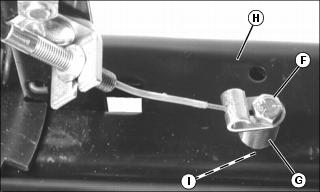
5. Install 1/4X1-1/2 in. hex bolt (F) through clevis lanyard fitting, .39 IDX.62 in. spacer (G) and left hole in push channel assembly (H). Secure with 1/4 in. lock nuts w/nylon insert (I).
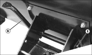
Install Spring Mount Rod
1. Using a hammer and a block of wood for support, install 3/8 in. palnut (A) onto spring mount rod (B).
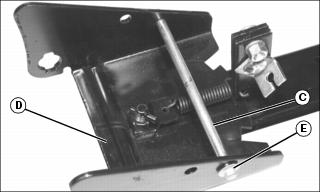
2. Insert spring mount rod (C) through holes nearest angle lock bars in push channel assembly (D).
3. Using a hammer and a block of wood for support, install 3/8 in. palnut (E) onto other end of spring mount rod.
Attach Blade to Push Channel Assembly
1. Install 1/8 in. cotter pin (A) through hole near bend in blade pivot shaft (B). Secure by spreading ends.
2. Align notched holes in push channel assembly (C) with notched holes in reinforcement plate (D).
3. With bend facing up, install blade pivot shaft (B) through notched holes from left.
4. Install 1/8 in. cotter pin (E) through end hole in blade pivot shaft. Secure by spreading ends.
Install Trip Spring
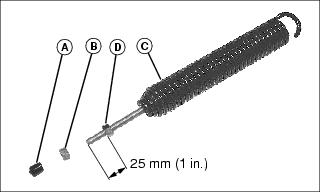
1. Remove plastic cap (A) and one 3/8 in. nut (B) from trip spring (C).
2. Adjust remaining 3/8 in. nut (D) so that 25 mm (1 in.) of threads are exposed.
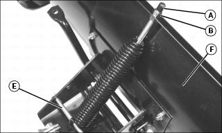
3. Hook trip spring around spring mount rod (E).
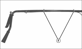
4. Insert threaded end of trip spring through hole in top edge of blade (F).
5. Install original 3/8 in. nut (B) and plastic cap (A).
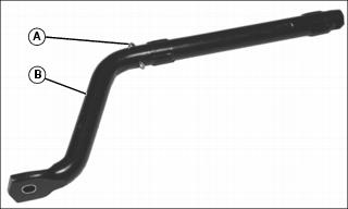
Attach Release Grip to Lift Handle Tube
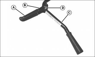
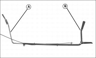
1. Install plastic grip (A) onto release grip (B).
NOTE: Release grip will bend inward while tightening lock nut. Release grip must pivot freely after installation.
2. Attach release grip to lift handle tube (C) using 5/16X1-1/2 in. hex bolt and 5/16 in. lock nut w/nylon insert (D). Do not over tighten. Release grip must pivot freely.
Attach Control Cable to Lift Handle Tube
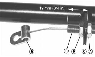
1. Install 5/16 in. jam nut (A) onto loose end of control cable (B) so that 19 mm (3/4 in.) of threads are exposed.
2. Insert control cable into cable mount bracket on lift tube handle (C).
3. Secure with 5/16 in. jam nut (D).
4. Insert ball end of control cable through clevis lanyard fitting (E).
NOTE: Clevis lanyard fitting must pivot freely after installation.
5. Install clevis lanyard fitting onto weld bolt on release grip (F) with 1/4 in. acorn nut (G). Do not over tighten-clevis lanyard fitting must pivot freely.
6. Secure control cable to lift tube handle with two tie straps (H).
Assemble Lift Handle Tube to Lift Handle Rod
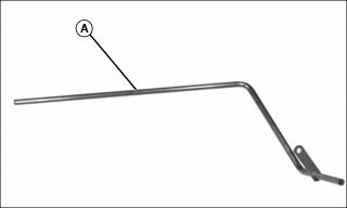
1. Lubricate long end of lift handle rod (A) using tube of grease.
2. Insert long end of lift handle rod (A) into lift handle tube (B).
Assemble Pivot Support
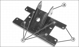
1. Attach pivot support bracket (A) to two angle support brackets (B) using four 3/8X1 in. hex bolts and 3/8 in. flanged lock nuts (C). Do not tighten.
2. Attach right hitch bracket (D) and left hitch bracket (E) to angle support brackets using four 3/8X1 in. hex bolts and 3/8 in. flanged lock nuts (F).
4. Install two 3/8X3/4 in. hex bolts (G) from inside of right and left hitch plates. Secure with 3/8 in. flanged lock nuts (H).