
Assembly
Identify Parts
Clear Plastic Bag Contains:
Bag of Parts Contains:
NOTE: There is an extra ignition key strapped to one of seat suspension springs.
Install Steering Wheel
1. Put front wheels in straight forward position.
3. Install steering wheel with logo in upright position.
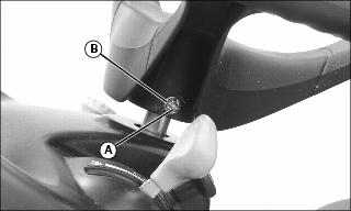
4. Install shoulder bolt (A). Drive bolt in until head of bolt contacts steering wheel.
5. Install washer and nut (B).
6. Tighten lock nut until it is snug. Do not tighten lock nut to pull washer or head of bolt into steering wheel.
Charge and Connect Battery
· Wear eye protection and gloves. · Do not allow direct metal contact across battery posts. |
1. Remove and discard the red positive (+) protective cap from the positive (+) battery terminal.
· Battery is fully charged at 12.6 volts.

3. Connect positive (+) battery cable (A) to battery.
4. Connect negative (-) battery cable (B).
5. Apply general purpose grease or silicone spray to terminal to help prevent corrosion.
6. Slide red cover over positive battery cable.
Check Tire Pressure
2. Check tire pressure with an accurate gauge.
3. Check that tires have equal air pressure. Add or remove air, if necessary.
Adjust Mower Level
Adjust mower level. (See Adjusting Mower Level in the OPERATING section.)
Check Engine Oil Level
Check engine oil level. (See Checking Engine Oil Level in the SERVICE ENGINE section.)
Check Machine Safety System
Perform safety system check to make sure the electronic safety interlock circuit is functioning properly. Perform all tests. (See Testing Safety System in the OPERATING section.)
Break-In Electric PTO Clutch
1. Start engine and move machine to flat level surface.

2. Push throttle lever (A) up to full throttle position.
3. Engage PTO (B) and allow mower to run for 10 seconds.
4. Disengage PTO and wait 10 seconds.