
Operating
Daily Operating Checklist
o Make sure all guards, deflectors and covers are in place and tightened.
o Check fuel stabilizer cartridge in fuel cap.
o Check that handle knobs are tight.
o Check for proper cutting height.
o Remove grass and debris from machine.
o Check area below machine for leaks.
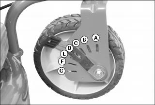
Adjusting Cutting Height
1. .Pull the height adjusting lever outward and move to the desired cutting height.
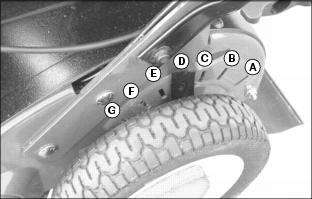
Picture Note: Left side shown.
• Front caster wheel adjustment.
2. Set all wheels at the same cutting height. The highest cutting height is location G. The lowest cutting height is location A.
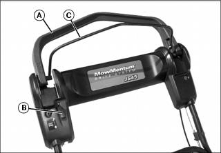
Adjusting Handle Height
1. Remove plastic knob (A), lock washer and carriage bolt securing lower handle (B) to mower deck bracket (C) at each side of mower deck. For first time set-up remove knob, washer and carriage bolt from pre-assembly position in mower deck brackets.
2. Align hole (D) on each side of lower handle with one of three height adjustment holes (E) in mounting brackets.
• Top hole (E) in mounting bracket will be highest handle position.
3. Install carriage bolt outward through hole in each mounting bracket and then through handle. Install lock washers, knobs and tighten to secure.
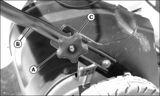
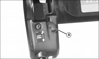
Locking Caster Wheel
NOTE: Each front caster is equipped with a lock mechanism. Lock both caster wheels into straight position when mowing on a slope to prevent mower from drifting.
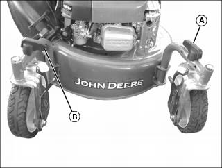
1. To LOCK caster wheels, push mower straight forward to align caster wheels and locking mechanisms, and turn both lock handles parallel with caster support (A) to engage lock.
2. To UNLOCK caster wheels, turn both lock handles 90° to caster support (B) to disengage lock.
Testing Safety Systems
The safety systems installed on your machine should be checked before each machine use. Be sure you have read the machine operator manual and are completely familiar with the operation of the machine before performing these safety system checks.
Use the following checkout procedures to check for normal operation of machine.
If there is a malfunction during one of these procedures, do not operate machine. See your authorized dealer for service.
Perform these tests in a clear open area. Keep bystanders away.
Testing Operator Presence Control
1. Hold the operator presence control against the drive handle.
3. Release operator presence control.
4. Listen for blade and engine to stop. Do not look under mower to check blade.
Starting and Stopping Engine
Starting Engine
1. Prime engine by pressing primer bulb on engine:
• Warm engine - Priming not necessary
2. Pivot the MOWMENTUM drive handle (A) all the way back.
3. Move the neutral lock (B) forward to LOCK.
4. Hold operator presence control (C) against drive handle.
5. Pull starter handle slowly until resistance is felt, then pull fast and steady.
NOTE: After engine has started, continue to hold operator presence control against drive handle or blade and engine will stop.
6. When engine starts, return rope slowly until starter handle is in bracket.
7. Move neutral lock back to UNLOCK and pivot the drive handle forward to engage drive system.
8. Pivot the drive handle forward to engage drive system.
Stopping Engine
1. Pull back on drive handle to disengage drive unit.
2. Release operator presence control.
Operating the Mower
NOTE: After the engine has been started, the operator presence control bar must be held against the drive handle to keep the engine running.
1. Start the engine, hold the operator presence control bar against the drive handle.
2. Move the drive handle forward to engage the drive or increase speed.
3. Move the drive handle back to decrease speed or stop.
4. Release the operator presence control bar to stop the engine and blade.
Emergency Stopping
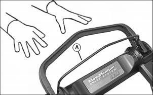
Release operator presence control (A) fully:
Using Neutral Lock
Picture Note: Shown in locked position.
When engaged, the neutral lock prevents the drive handle from moving forward and engaging the drive unit.
Use the neutral lock to lock the drive handle in a stationary position for transporting the machine or operating in a push mode. The neutral lock should not be used to lock the drive handle in the forward position.
To engage the neutral lock, pull the drive handle all the way back, and push the neutral lock (A) fully forward. This will prevent the drive handle from moving forward and unexpectedly engaging the drive unit.
To disengage the neutral lock, simply pull the lever fully backward. This will allow the drive handle to operate normally.
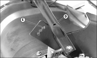
Installing Side Discharge Deflector

2. Remove knob (A) and washer securing side discharge cover (B).
3. Raise and hold up side discharge cover.
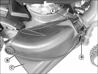
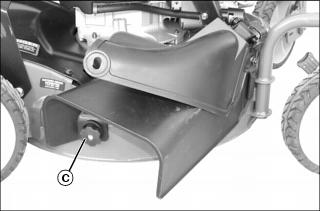
4. Install side discharge deflector (C) below side discharge cover (B) and align lower mounting tab on outside front of deflector under side discharge cover hinge bracket arm (D).
5. Install slot on inside front of deflector under restraining nut (E) on top of deck (under right front corner of engine).
6. Install mounting hole on inside rear of deflector onto stud behind rear of discharge opening, where rear of side discharge cover was originally secured.
7. Install knob (A) and washer, removed earlier, on stud and tighten securely.
8. Release side discharge cover and allow it to rest against side discharge deflector.
Installing Grass Bag
Installing Grass Bag Adapter
NOTE: Grass bag adapter must be installed before using grass bag.
2. Remove knob and washer securing side discharge cover. (See “Using Side Discharge Deflector”.)
3. Raise and hold side discharge cover.
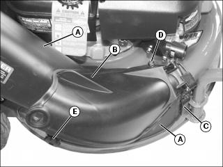
4. Install grass bag adapter (A) below side discharge cover (B) and align lower mounting tab on outside front of deflector under side discharge cover hinge bracket arm (C).
5. Install slot on inside front of deflector under restraining nut (D) on top of deck (under right front corner of engine).
6. Install mounting hole on inside rear of deflector onto stud behind rear of discharge opening, where rear of side discharge cover was originally secured.
7. Install knob (E) and washer, removed earlier, on stud and tighten securely.
8. Release side discharge cover and allow it to rest against grass bag adapter.
Installing Grass Bag
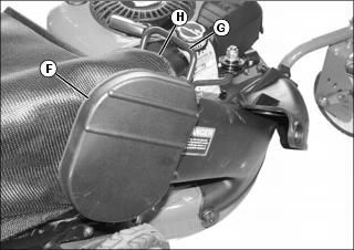
1. Open adapter door (F), grasp grass bag connector handle (G) and slide grass bag connector (H) down over adapter flange to secure. Release adapter door to rest against grass bag.
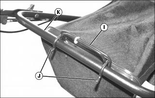
2. Grasp grass bag handle (I), pull grass bag back and position grass bag hooks (J) over lower handle cross bar (K).
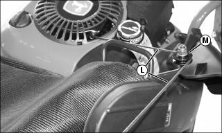
3. Pull operator presence control back to the drive handle, pull starter cord (L) out, route to pulley (M), mounted on grass bag adapter, and up to rope guide located on right side of upper handle.
Using the Mower for Mulching
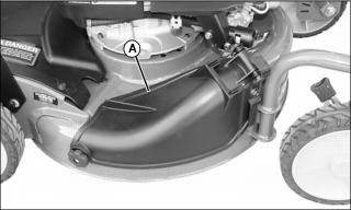
2. Make sure side discharge cover (A) is closed.
3. Adjust cutting height to remove only 1/3 of the grass at at time.