
Operating
Daily Operating Checklist
o Test safety systems. Perform safety interlock system checkout procedure.
o Check transmission oil level.
o Check coolant level on liquid cooled engine.
o Remove grass and debris from machine.
o Check area below machine for leaks.
Avoid Damage to Plastic and Painted Surfaces
· Do not wipe plastic parts unless rinsed first.
· Insect repellent spray may damage plastic and painted surfaces. Do not spray insect repellent near machine.
· Be careful not to spill fuel on machine. Fuel may damage surface. Wipe up spilled fuel immediately.
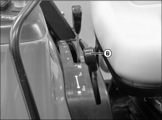
Operator Station (Gear Models)

B - Engine Speed Foot Throttle
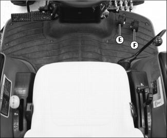
E - Dual Selective Control Valve (SCV) Lever
F - Rockshaft Adjustable Depth Stop Knob
I - Transmission Range Shift Lever
J - Transmission Gear Shift Lever
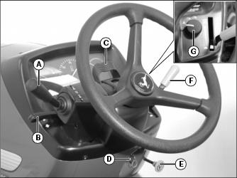
A - Reverser Lever (ePowrReverser Model)
C - Tilt Steering Control Lever
F - Engine Speed Hand Throttle Lever
Operator Station (Hydrostatic Model)

E - Dual Selective Control Valve (SCV) Lever
F - Rockshaft Adjustable Depth Stop Knob
I - Transmission Range Shift Lever
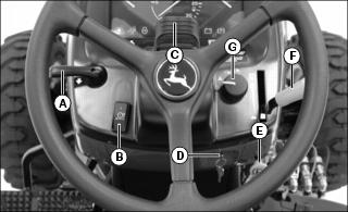
C - Tilt Steering Control Lever
F - Engine Speed Hand Throttle Lever
Right Side Panel Controls (Machines With Standard Cruise Control Installed)

Picture Note: All controls shown may not be installed on your machine.
Right Side Panel Controls (Machines With Automotive Cruise Control Option Installed)

Picture Note: All controls shown may not be installed on your machine.
Right Side Panel Controls (Machines With SpeedMatch Option Installed)
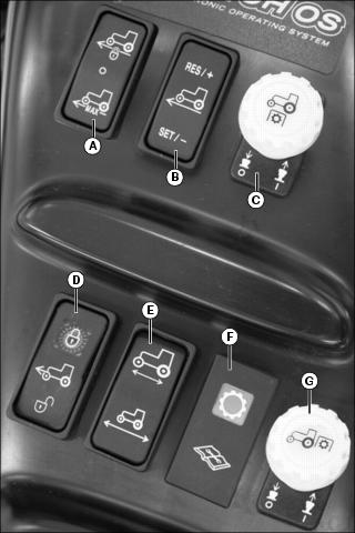
Picture Note: All controls shown may not be installed on your machine.
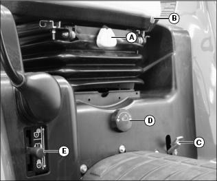
Floor Panel Controls (Gear Models)

A - Operator Seat Height Adjustment Knob
B - Operator Seat Adjustment Lever
C - MFWD Control Lever (SyncShift model only)
D - Rockshaft Rate-of-Drop Control Knob
F - Selective Control Valve (SCV) Lock Lever
Floor Panel Controls (Hydrostatic Model)
A - Operator Seat Height Adjustment Knob
B - Operator Seat Adjustment Lever
D - Rockshaft Rate-of-Drop Control Knob
E - Selective Control Valve (SCV) Lock Lever
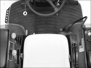
Using Step
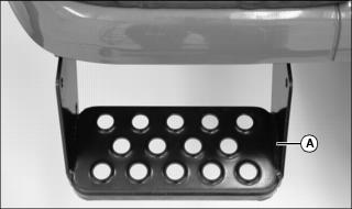
Step (A) is located on the left side of machine. Use step for entering and exiting the operator station.
Adjusting Seat
Before starting engine to operate machine, adjust operator seat position, height and suspension.
Adjusting Seat Position
2. Move seat lever (A) to the left.
3. Slide seat forward or rearward to desired position.
4. Release lever to lock seat in position. Make sure all controls can be easily accessed.
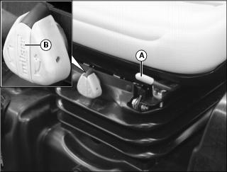
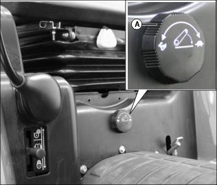
Adjusting Seat Height and Tension
1. Flip out handle (B) on height adjustment knob.
· Turn handle clockwise to raise operator seat and increase spring tension.
· Turn handle counterclockwise to lower operator seat and decrease spring tension.
2. Return handle to closed position.
Using Seat Belt
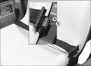
Fasten Belt
1. Pull belt end across operator lap.
2. Install tab into buckle (A).
· A click will be heard when the tab locks into the buckle.
Release Belt
1. Press red button (B) to release seat belt allowing the belt to automatically retract.
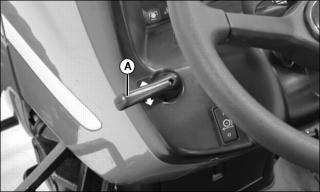
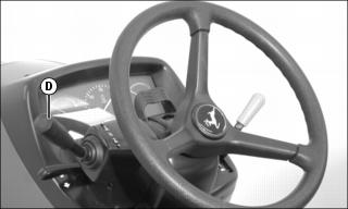
Adjusting Tilt Steering Wheel
1. Park machine safely. (See Parking Safely in the SAFETY section.)

2. Pull tilt steering control lever (A) forward to release steering wheel.
3. Adjust steering wheel to desired position.
4. Release tilt steering control lever to lock steering wheel in position.
Using Light Switch

B - Warning flasher lights on.
C - Road Position: headlights, taillights, and warning flasher lights on.
D - Field Position: headlights, taillights, and optional working lights on.
Using Key Switch
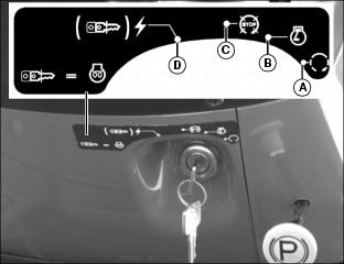
IMPORTANT: Avoid damage! There is an accessory key switch position (D) to the left of the key switch off position. Do not move the key switch to this position. The battery could be drained. |
Using the Instrument Panel

· Rated Engine Speed: 2600 rpm
Understanding Indicator Lamp Codes

Picture Note: All controls shown may not be installed on your machine.
The indicator lamp (A) will display a combination of flashes in sequence to indicate faults in the electrical system. More than one sequence may be displayed in the event of multiple electrical faults.
A flashing trouble code does not signify potential for machine damage. Codes may flash for minor reasons: an ePowrReverser model clutch is not depressed prior to operation, eHydro model forward and reverse travel pedals are depressed simultaneously, the operator is off the seat or eHydro travel pedals are depressed briefly while the transmission is in neutral, etc.
Turning off the machine and restarting should eliminate most trouble codes. If the indicator lamp continues to flash but the machine can be operated, you may continue to operate without causing damage. Contact your John Deere dealer when convenient.
Using Turn Signal Lever
· Pull the turn signal lever (A) down to signal a left turn.
· Push the turn signal lever (A) up to signal a right turn.
Testing Safety Systems
Use the following checkout procedure to check for normal operation of machine.
If there is a malfunction during one of these procedures, Do not operate machine. See your John Deere dealer for service.
Perform these tests in a clear open area. Keep bystanders away.
Testing Neutral Start Switch (Gear Models Only)
3. Push the rear and mid-PTO knobs to the disengaged/off position.
4. Depress clutch pedal completely and:
· Move the transmission range shift lever to the N (neutral) position.
· Move the transmission gear shift lever to any position other than N (neutral) position.
5. Turn key switch to start position.
6. Turn key switch to off position and move transmission gear shift lever to the N (neutral) position.
Testing Seat Switch (Gear Models Only)
3. Push the rear and mid-PTO knobs to the disengaged/off position.
4. Depress clutch pedal completely and move the transmission range and gear shift levers into the N (neutral) position.
5. Start machine engine. Set engine speed at 1500 rpm.
6. Depress clutch pedal completely and:
· All Models: move the transmission gear shift lever to any position other than N (neutral) position.
· ePowrReverser Model: move the reverser lever to the forward or reverse position.
7. Raise up from operator's seat while depressing clutch pedal completely.
9. Turn key switch to off position and move transmission gear shift lever to the N (neutral) position.
Testing Rear PTO Knob
3. Push the rear and mid-PTO knobs to the disengaged/off position.
4. Gear Models: Depress clutch pedal completely and move the transmission range and gear shift levers to the N (neutral) position.
5. Pull the rear PTO knob to the engaged/on position.
6. Turn key switch to start position.
7. Push the rear PTO knob to the disengaged/off position.
8. Turn key switch to off position.
Testing Rear PTO/Seat Switch Interface
3. Push the rear and mid-PTO knobs to the disengaged/off position.
4. Gear Models: Depress clutch pedal completely and:
· All Models: move the transmission range and gear shift levers into the N (neutral) position.
· ePowrReverser Model: move the reverser lever to the center neutral position.
6. Gear Models: Release clutch pedal.
7. Pull the rear PTO knob to the engaged/on position.
8. Raise up from operator's seat. Do not dismount machine.
9. Engine should stop. Engine shut-off solenoid must de-energize in 1/2 second, causing the engine to stop.
10. Push the rear PTO knob to the disengaged/off position.
11. Turn key switch to off position.
Testing Mid-PTO/Seat Switch Interface
3. Push the rear and mid-PTO knobs to the disengaged/off position.
4. Gear Models: Depress clutch pedal completely and:
· All Models: move the transmission range and gear shift levers into the N (neutral) position.
· ePowrReverser Model: move the reverser lever to the center neutral position.
5. Start machine engine. Set engine speed at 1500 rpm.
6. Gear Models: Release the clutch.
7. Raise up from operator's seat. Do not dismount machine.
8. Pull the mid-PTO knob to the engaged/on position.
9. Pull the rear PTO knob to the engaged/on position.
10. Engine should begin to stop.
Testing Rear PTO/Park Brake Interface
3. Push the rear and mid-PTO knobs to the disengaged/off position.
4. Gear Models: Depress clutch pedal completely and:
· All Models: move the transmission range and gear shift levers into the N (neutral) position.
· ePowrReverser Model: move the reverser lever to the center neutral position.
5. Start machine engine. Set engine speed at 1500 rpm.
6. Gear Models: Release clutch pedal.
7. Raise up from operator's seat. Do not dismount machine.
8. Pull the rear PTO knob to the engaged/on position.
10. Engine should begin to stop.
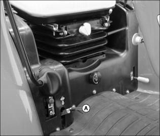
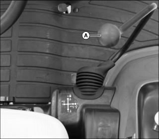
Using Fuel Shut-Off Valve
Close the valve when performing any type of engine service, during transport of the machine, and during storage.
2. Remove side panel from right side of engine.
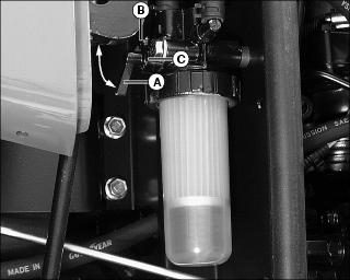
3. Open or close fuel shut-off valve lever (A) as required:
Using Brake Pedals (Gear Models)
Using Brake Pedals As Driving Brake:
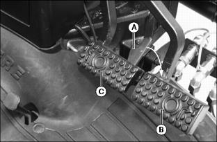
1. Rotate brake pedal latch (A) clockwise until it locks into right turn brake pedal (B).
2. Depress either brake pedal to slow or stop the machine.
· With latch down, brakes should stop machine in a straight line.
Using Brake Pedals to Assist In Turning:
IMPORTANT: Avoid damage! Do not apply turn brakes while an implement is engaged with the ground. Damage to the 3-point hitch and implement may occur. |
NOTE: Turn brake pedals can be used to make tighter turns and may reduce unnecessary backing.
1. Rotate brake pedal latch (A) counterclockwise until it stops against left turn brake pedal (C). The brake pedals will now function independently.
· To make a tighter left turn, depress left turn brake pedal (C) while turning to the left.
· To make a tighter right turn, depress right turn brake pedal (B) while turning to the right.
Using Brake Pedals (Hydrostatic Model)
Using Brake Pedals As Driving Brake:

1. Rotate brake pedal latch (A) counterclockwise until it locks into left turn brake pedal (B).
2. Depress either brake pedal to slow or stop the machine.
· With latch down, brakes should stop machine in a straight line.
Using Brake Pedals to Assist In Turning:
IMPORTANT: Avoid damage! Do not apply turn brakes while an implement is engaged with the ground. Damage to the 3-point hitch and implement may occur. |
NOTE: Turn brake pedals can be used to make tighter turns and may reduce unnecessary backing.
1. Rotate brake pedal latch (A) clockwise until it stops against right turn brake pedal (C). The brake pedals will now function independently.
· To make a tighter left turn, depress left turn brake pedal (B) while turning to the left.
· To make a tighter right turn, depress right turn brake pedal (C) while turning to the right.
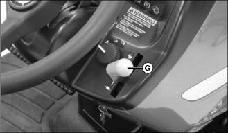
Using Park Brake
Locking Park Brake:
1. Lock both brake pedals together using brake pedal latch.
2. Press down completely on brake pedals with foot.
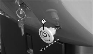
3. Pull park brake lock (A) completely out to the locked position.
4. Remove foot from brake pedals. Both pedals should now stay down in the locked position.
Unlocking Park Brake:
1. Press down completely on brake pedals with foot.
2. Push park brake lock completely in to the unlocked position.
3. Remove foot from brake pedals. Both pedals should now be released from the locked position.
Using Throttle Controls
Hand Throttle Operation
Use the hand throttle lever to set a constant engine speed for stationary operation (all models) or for field operation such as tillage (gear transmission only).
· Rated Engine Speed - 2600 rpm
Foot Throttle Operation (Gear Models Only)
Use the foot throttle to temporarily override/increase the hand throttle lever setting when the machine operation requires repeated engine speed change, such as when operating a loader.
1. Set the hand throttle lever at middle operating rpm.
2. Depress the foot throttle (A) to increase rpm and machine speed.
3. Release the foot throttle to return engine speed to the previously-set hand throttle lever position.
Starting the Engine
NOTE: It is recommended to install optional engine block heater and hydraulic oil heater if operating machine in temperatures below -18° C (0° F).
If temperature is below 5° C (40° F), follow the cold weather starting steps in this section.
1. Open the fuel shut-off valve.
Picture Note: All controls shown may not be installed on your machine.
3. Push the rear (A) and mid-PTO (B) knobs to the disengaged/off position.
4. Move transmission to neutral position:

Picture Note: SyncShift Model Shown.
· All gear models: Depress clutch pedal completely and move the transmission gear lever (C) to the N (neutral) position.
· ePowrReverser model: move the reverser lever (D) to neutral position.
· eHydro model: remove foot from forward (E) and reverse (F) travel pedals.
5. Lower any rear mount or midmount implement to the ground by pushing the rockshaft control lever forward.
6. Lower any front mounted implement to the ground using the SCV lever.
7. Set hand throttle lever (G) to the 1/3 fast position.
8. Turn ignition key switch to the run position.
9. Check instrument panel indicator lights:
· Alternator/battery charging light will glow.
· Park brake light will illuminate if park brake is locked.
· Engine oil pressure light will glow.
10. For cold weather starting, use the intake air heater system. Activate the intake air heater system by pushing in the ignition key switch with the key, and holding it there for the required time:
· 10 - 15 seconds for temperatures as low as -18° (0°F).
· 15 - 30 seconds for temperatures below -18° (0°F).
11. Turn key switch to the start position. Release key when engine starts.
12. Check instrument panel indicator lights:
· Engine oil pressure light should go out within 5 seconds.
NOTE: Set engine speed at full throttle if indicator light does not go out after 10 seconds.
· Alternator/battery charging light should go out within 10 seconds.
· If indicator lights stay on longer than the given time intervals, stop the engine and check for cause.
IMPORTANT: Avoid damage! In cold weather, run engine several minutes to allow engine oil and transmission oil to warm. |
NOTE: It is normal for the engine to be louder and for blue-white exhaust smoke to be present during engine warm-up. The amount of exhaust smoke depends on air temperature.
· In warm weather, set hand throttle lever to the 1/2 fast position for 1 minute without load.
· In cold weather, set hand throttle lever to the 1/2 fast position for 5 minutes without load.
Idling the Engine
NOTE: Allowing engine to idle for long periods of time will waste fuel and cause carbon build-up.
1. Adjust hand throttle lever to set engine speed at 950 rpm (slow idle speed).
Starting a Stalled Engine
IMPORTANT: Avoid damage! If engine stalls while operating under load, start engine immediately to prevent abnormal heat build-up in engine. |
1. Push the rear and mid-PTO knobs to the disengaged/off position.
2. Move transmission to neutral position:
· All gear models: Depress clutch pedal completely and move the transmission gear lever to the N (neutral) position.
· ePowrReverser model: move the reverser lever to neutral position.
· eHydro model: remove foot from forward travel and reverse travel pedals.
3. Start engine. Continue with normal operation, or set engine at 950 rpm (slow idle speed) for 2 minutes before stopping the engine.
Stopping the Machine
Normal Stopping
1. Position the machine on a firm, level surface.
· All gear models: Depress clutch pedal completely and depress both brake pedals.
· Hydrostatic model: Remove foot smoothly from forward or reverse travel pedals to stop motion.
3. Move transmission to neutral position:
· All gear models: Depress clutch pedal completely and move the transmission gear lever to the N (neutral) position.
· ePowrReverser model: move the reverser lever to neutral position.
4. Push the rear and mid-PTO knobs to the disengaged/off position.
5. Lower any rear or midmount implement to the ground by pushing rockshaft control lever forward.
6. Lower any front implement to the ground by using the SCV lever.
IMPORTANT: Avoid damage! Do not stop engine immediately after hard or extended operation. Keep engine running at 950 rpm for about 2 minutes to prevent heat build-up. |
7. Adjust hand throttle lever rearward to set engine speed at 950 rpm (slow idle speed). Allow engine to idle for 2 minutes.
8. Lock the brake pedals together using the brake pedal latch.
10. Turn ignition key switch to the off position.
12. Wait for the engine and all moving parts to stop before leaving the operator's station.
Emergency Stopping (Gear Models)
1. Depress clutch pedal all the way down and depress both brake pedals.
2. Turn key switch to off position. Do not release clutch pedal until all moving parts have stopped.
3. If possible, lock the park brake.
Emergency Stopping (Hydrostatic Model)
1. Remove foot from forward or reverse travel pedals.
3. Turn key switch to off position. Do not release brake pedals until all moving parts have stopped.
4. If possible, lock the park brake.
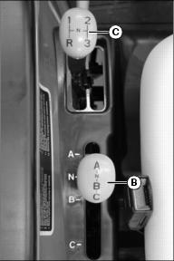
Operating the SyncShift Transmission

The range shift lever (A) provides three speed ranges. The gear shift lever (B) provides three forward gears and one reverse gear.
Use both the shift levers in different combinations to achieve nine forward and three reverse speeds.
Machine motion must stop and the clutch pedal must be depressed before changing ranges.
1. Choose a speed range to match the work application:
· A - Low speed/high power operations such as tilling hard soil, mowing high grass, positioning backhoe, etc.
· B - Operations including moderate tilling, hauling, and grass mowing.
· C - High speed operations such as transport and light mowing.
2. Choose a gear that matches the immediate power/speed requirements:
· 1st Gear - High power, low speed operations.
· 2nd Gear - Medium power, moderate speed operations.
· 3rd Gear - Low power, high speed operations.
· Reverse - Backing up and positioning operations.
Driving Machine (SyncShift Model)
3. Depress clutch pedal (A) completely.
4. Choose A, B, or C speed range on transmission range shift lever (B) to match work application.
5. Move the transmission gear shift lever (C) to first gear or (R) reverse gear position.
6. Release clutch pedal gradually to take up load smoothly.
7. Continue to shift gears while moving under normal loads:
· Depress clutch pedal completely and shift to next gear.
· Release clutch pedal gradually to take up load smoothly.
· To maintain a constant operating speed, adjust the engine speed with the hand throttle lever.
· To repeatedly increase and decrease engine speed, leave the hand throttle lever set at the middle position and use the foot throttle to change engine speed.
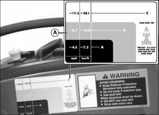
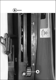
Travel Speeds

Picture Note: Decal shown on hydrostatic model.
The ground speed decal (A) located on the right fender can be used to determine your travel speed.
If the tire size on your machine is within the range indicated on the label, and you are traveling with the engine speed at the rpm indicated on the label, the approximate travel speed for each range and/or gear is shown.
Operating the ePowrReverser Transmission
The range shift lever (A) provides three speed ranges. The gear shift lever (B) provides four gear positions. The reverser lever (C) controls travel direction.
Use all three levers in different combinations to achieve twelve forward and twelve reverse speeds.
Machine motion must stop and the clutch pedal must be depressed before changing ranges. Gears may be changed while machine is in motion if clutch pedal is completely depressed.
1. Choose a speed range to match work application:
· A - Low speed/high power operations such as tilling hard soil, mowing high grass or positioning backhoe.
· B - Operations including moderate tilling, hauling, and grass mowing.
· C - High speed operations such as transport and light mowing.
2. Choose a gear that matches the immediate power/speed requirements:
· 1st Gear - High power, low speed operations.
· 2nd Gear - Medium power, moderate speed operations.
· 3rd Gear - Low power, moderate speed operations.
· 4th Gear - Low power, high speed operations.
Driving Machine (ePowrReverser Model)

2. Move reverser lever (A) to neutral position.
4. Depress clutch pedal (B) completely.
5. Choose A, B, or C speed range on transmission range shift lever (C) to match work application.
6. Move the transmission gear shift lever (D) to the desired gear position.
7. Move the reverser lever (A) to the forward or reverse position.
8. Release clutch pedal gradually to take up load smoothly.
9. Continue to shift gears while moving under normal loads:
· Depress clutch pedal completely and shift to next gear.
· Release clutch pedal gradually to take up load smoothly.
· To maintain a constant operating speed, adjust the engine speed with the hand throttle lever.
· To repeatedly increase and decrease engine speed, leave the hand throttle lever set at the middle position and use the foot throttle to change engine speed.
11. To change travel direction:
· Move the reverser lever to the forward or reverse position.
Travel Speeds
Picture Note: Decal shown on hydrostatic model.
The ground speed decal (A) located on the right fender can be used to determine your travel speed.
If the tire size on your machine is within the range indicated on the label, and you are traveling with the engine speed at the rpm indicated on the label, the approximate travel speed for each range and/or gear is shown.
Operating the eHydro Transmission
The range shift lever (A) provides three speed ranges.
The range shift lever is used in conjunction with the forward (B) and reverse (C) travel pedals.
1. Choose a speed range to match work application.
· A - Low speed/high power operations such as tilling hard soil, mowing high grass or positioning backhoe.
· B - Operations including moderate tilling, hauling, and grass mowing.
· C - High speed operations such as transport and light mowing.
Driving Machine (eHydro Model)
IMPORTANT: Avoid damage! To prevent transmission damage, stop machine motion completely before shifting the range shift lever. |

3. Choose A, B, or C speed range on transmission range shift lever (A) to match work application.
4. Move hand throttle lever to desired operating speed.
5. Slowly depress pedal (B) downward to travel forward. Slowly depress pedal (C) downward to travel in reverse.
· The farther either travel pedal is depressed, the faster the machine will travel.
6. Release travel pedal to stop machine and change speed range.
7. Fully stop machine motion before turning off ignition.
Travel Speeds

Picture Note: Decal shown on hydrostatic model.
The ground speed decal (A) located on the right fender can be used to determine your travel speed.
If the tire size on your machine is within the range indicated on the label, and you are traveling with the engine speed at the rpm indicated on the label, the approximate travel speed for each range and/or gear is shown.
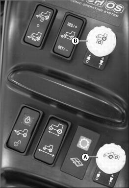
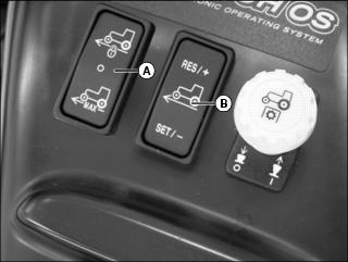
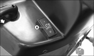
Using Cruise Control (eHydro Model With Standard Cruise Control)
NOTE: The cruise control is only operational when the machine is traveling forward.
Engaging Cruise Control
1. Depress forward travel pedal until desired travel speed is reached.

Picture Note: All controls shown may not be installed on your machine.
2. Fully depress top of cruise switch (A) to engage cruise control.
· Instrument panel cruise control indicator light will illuminate when cruise control is activated.
3. Release forward travel pedal.
4. To adjust travel speed, disengage cruise control and engage cruise control again at a different speed.
Disengaging Cruise Control
NOTE: The machine will stop if cruise control is disengaged while the machine is in motion. To maintain forward motion, depress the forward travel pedal before disengaging cruise control.
1. Fully depress bottom of cruise switch (A) to return switch to middle position, or depress the right brake pedal.
· Instrument panel cruise control indicator light should go out when the cruise control is disengaged.
Using Cruise Control (eHydro Model With Automotive Cruise Control Option)
NOTE: The cruise control is only operational when the machine is traveling forward.
Engaging Cruise Control
1. Depress forward travel pedal until desired travel speed is reached.

Picture Note: Top photo shows controls on machine with SpeedMatch option. Bottom photo shows controls on machine without SpeedMatch option. All controls shown may not be installed on your machine.
2. Fully depress top of cruise switch (A) to activate cruise control.
3. Fully depress bottom of accel/decel switch (B) to set cruise speed.
· Instrument panel cruise control indicator light will illuminate when cruise control is set.
4. Release forward travel pedal.
5. Adjust cruise travel speed:
· Fully depress top of accel/decel switch (B) repeatedly to increase speed by increments.
· Fully depress bottom of accel/decel switch (B) repeatedly to decrease speed by increments.
NOTE: Machine must be moving forward, not stopped, for resume function to operate.
6. Fully depress top of accel/decel switch (B) to resume cruise speed after cruise control has been disengaged.
Disengaging Cruise Control
NOTE: The machine will stop if cruise control is disengaged while the machine is in motion. To maintain forward motion, depress the forward travel pedal before disengaging cruise control.
1. Fully depress bottom of cruise switch (A) to return switch to middle position, or depress the right brake pedal.
· Instrument panel cruise control indicator light should go out when the cruise control is disengaged.
Using SpeedMatch Option (eHydro Model)
SpeedMatch enables the operator to set the desired maximum travel speed for the machine. Full forward or reverse pedal travel distance can be used to control machine travel speed between stop and the desired maximum travel speed.
1. Depress forward travel pedal until desired maximum travel speed is reached.

Picture Note: All controls shown may not be installed on your machine.
2. Fully depress bottom of cruise switch (A) to activate speedmatch function.
3. Fully depress bottom of accel/decel switch (B) to set maximum travel speed.
4. Release forward travel pedal. Completely depress forward travel pedal to achieve desired maximum speed.
5. Adjust maximum travel speed:
· Fully depress top of accel/decel switch (B) repeatedly to increase speed by increments.
· Fully depress bottom of accel/decel switch (B) repeatedly to decrease speed by increments.
6. Fully depress top of cruise switch (A) to return switch to middle position and disengage speedmatch.
Using LoadMatch (eHydro Model)
LoadMatch enables the operator to prevent the engine stalling during heavy load applications such as operating with a loader.
1. Fully depress top of switch (A) to engage LoadMatch.
2. Fully depress bottom of switch (A) to disengage LoadMatch.
Using MotionMatch
MotionMatch enables the operator to adjust machine acceleration and deceleration rates. Shorter starting and stopping distances can be set for applications requiring rapid changes in direction, such as operating with a loader. Longer starting and stopping distances can be set to avoid turf damage in other applications.
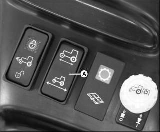
Picture Note: All controls shown may not be installed on your machine.
1. Fully depress top of switch (A) for quicker acceleration/deceleration response levels, and to reduce machine starting/stopping distances.
2. Fully depress bottom of switch (A) for slower acceleration/deceleration response levels and to increase machine starting/stopping distances.
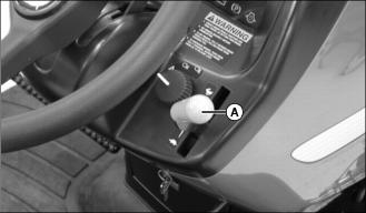
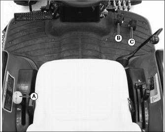
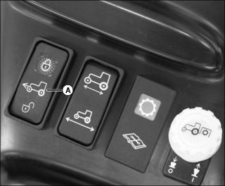
Using Differential Lock
To prevent tipping, do not engage differential lock under any of the following conditions: |
The differential lock is used to provide better traction when the rear wheels start to slip. Engaging the differential lock will lock the right and left side rear axles together and cause both rear wheels to turn at equal speeds for maximum traction.
NOTE: Turning radius is increased when the differential lock is engaged. To assist turning, release the differential lock and use the turn brake pedals.
Engaging Differential Lock
1. Stop or slow machine movement.
NOTE: Differential lock will remain engaged as long as rear wheel slippage occurs. If tires slip and regain traction repeatedly, hold down pedal with foot so differential lock remains engaged.
Picture Note: Gear model shown. Differential lock pedal is located on left side of floor panel controls on hydrostatic model.
2. Push down on differential lock pedal (A) to engage differential lock.
Disengaging Differential Lock
1. Remove foot from differential lock pedal.
NOTE: Rear wheel slippage will keep differential lock engaged. Lock will automatically disengage when traction equalizes.
2. If lock does not disengage when foot is removed from pedal, depress one turn brake pedal and then the other.
Using Mechanical Front Wheel Drive (MFWD)
Mechanical front wheel drive (MFWD) enables the powertrain to drive all four wheels for improved traction on difficult ground conditions and provides 4-wheel braking. MFWD can be engaged and disengaged on-the-go with light loads and on low traction surfaces.
NOTE: On eHydro and ePowrReverser models, a "pop" sound may be heard when MFWD is engaged. This is normal for MFWD operation.
SyncShift Model

1. Raise the MFWD control lever (A) to engage MFWD.
NOTE: It may be necessary to reduce engine load to disengage front wheel drive.
2. Lower MFWD control lever (A) to disengage MFWD.
All Models Except SyncShift
Picture Note: All controls shown may not be installed on your machine.
1. Fully depress top of MFWD switch (A) to engage MFWD.
NOTE: It may be necessary to reduce engine load to disengage front wheel drive.
2. Fully depress bottom of MFWD switch to disengage MFWD.
Tips for Operating MFWD:
· Maintain front tire pressure at maximum allowable level to ensure proper tire performance in all field conditions.
· Engage MFWD to provide four-wheel braking.
· Disengage MFWD when driving machine to or from work site to increase front tire life.
Using the Power-Take-Off (PTO) Safely

Using Rear and Mid-PTO (Operator on Seat)
NOTE: The mid-PTO is available as optional equipment, and is only operational with the operator on the seat.
Engaging Rear PTO
· Syncshift model: Depress clutch pedal completely and move the transmission gear shift lever to the N (neutral) position.
· ePowrReverser model: move the reverser lever to neutral position.
· eHydro model: remove foot from forward and reverse travel pedals.

Picture Note: All controls shown may not be installed on your machine.
3. Push the rear (A) and mid (B) PTO knobs to the disengaged/off position.
NOTE: The starter will not crank if the rear PTO knob is pulled to the engaged/on position. If the operator leaves the seat with the engine running and the rear PTO engaged, the safety interlock system will stop the engine and all implements.
4. Reduce throttle setting to 1500 rpm.
5. Pull the rear PTO knob (A) to the engaged/on position to engage the rear PTO.
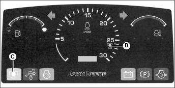
· The instrument panel PTO engaged light (C) will illuminate when the rear PTO is engaged.
6. Adjust the hand throttle lever forward to the desired speed for implement used.
NOTE: The tachometer indicates a standard 540 PTO (D) at engine speed of 2600 rpm.
Disengaging Rear PTO
1. Adjust engine rpm to 950 (low idle).
2. Push the rear PTO knob (A) to the disengaged/off position to disengage the rear PTO.
· The instrument panel PTO engaged light (C) will go out when the rear PTO is disengaged.
Engaging Mid-PTO
IMPORTANT: Avoid damage! Do not engage the mid-PTO while the rear PTO is engaged. Engage the mid-PTO first. |
· Syncshift model: Depress clutch pedal completely and move the transmission gear shift lever to the N (neutral) position.
· ePowrReverser model: move the reverser lever to neutral position.
· eHydro model: remove foot from forward and reverse travel pedals.

Picture Note: All controls shown may not be installed on your machine.
3. Push the rear (A) and mid (B) PTO knobs to the disengaged/off position.
NOTE: The starter will not crank if the rear PTO knob is pulled to the engaged/on position. If the operator leaves the seat with the engine running and the rear PTO engaged, the safety interlock system will stop the engine and all implements.
4. Reduce throttle setting to 1500 rpm or less.
5. Pull the mid-PTO knob (B) to the engaged/on position.
NOTE: The mid-PTO will only function when both the mid-PTO and rear PTO are engaged.
6. Pull the rear PTO knob (A) to the engaged/on position.

· The instrument panel PTO engaged light (C) will illuminate when the rear PTO is engaged.
7. Adjust the hand throttle lever forward to the desired speed for implement used.
NOTE: The tachometer indicates a standard 540 PTO (D) at engine speed of 2600 rpm. At 540 rpm rear PTO, mid-PTO speed will be 2100 rpm.
Disengaging Mid-PTO
IMPORTANT: Avoid damage! Do not disengage mid-PTO while rear PTO is engaged. Disengage rear PTO first. |
1. Adjust engine rpm to 950 (low idle) or less.
2. Push the rear PTO knob (A) to the disengaged/off position to disengage the rear PTO.
· The instrument panel PTO engaged light (C) will go out when the rear PTO is disengaged.
3. Push the mid-PTO knob (B) to the disengaged/off position to disengage the mid-PTO.
Using Rear PTO (Operator off Seat)
NOTE: The rear PTO can be engaged with the operator off the seat. The Safety Interlock System will stop the engine and all implements if the mid-PTO is engaged and the operator gets off the seat.
2. Move transmission to neutral position:
· All gear models: Depress clutch pedal completely and move the transmission gear and range shift levers to the N (neutral) position.
· ePowrReverser model: move the reverser lever to neutral position.
· eHydro model: move the range shift lever to the N (neutral) position.
Picture Note: All controls shown may not be installed on your machine.
4. Push the rear (A) and mid (B) PTO knobs to the disengaged/off position.
NOTE: The starter will not crank if the rear PTO knob is pulled to the engaged/on position.
5. Start the engine and adjust speed to 1500 rpm.
6. Get off the operator's seat.
7. Pull the rear PTO knob (A) to the engaged/on position to engage the PTO.
· The engine should continue to run.

· The instrument panel PTO engaged light (C) will illuminate when the rear PTO is engaged.
8. Adjust the hand throttle lever forward to the desired speed for implement used.
NOTE: The tachometer indicates a standard 540 PTO (D) at engine speed of 2600 rpm.
Disengaging Rear PTO
1. Adjust engine rpm to 950 (low idle) or below.
2. Push the rear PTO knob (A) to the disengaged/off position to disengage the rear PTO.
· The instrument panel PTO engaged light (C) will go out when the rear PTO is disengaged.
Using Drawbar Hitch
IMPORTANT: Avoid damage! Maximum static vertical load on drawbar should not exceed the maximum recommendations. Drive slowly with heavy loads. |
Maximum Drawbar Loads
Certain heavy equipment such as a loaded single-axle trailer can place excessive strain on the drawbar. Strain is greatly increased by speed and rough ground. Do not exceed the following maximum static vertical loads on drawbar:
· All Models...............................................255 kg (562 lb)
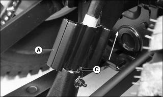
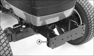
Adjusting Drawbar Length
IMPORTANT: Avoid damage! For drawn PTO-driven implements, the drawbar must be in the operating position. |
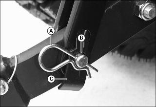
The drawbar is equipped with two adjusting holes for changing drawbar length and one hole for storage.
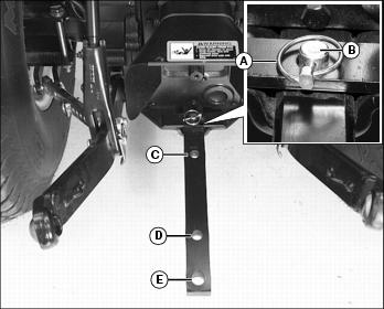
1. Remove quick-lock pin (A) and drilled pin (B).
2. Adjust drawbar to operating position (C) or (D), or to storage position (E).
3. Install drilled pin (B) up from bottom of machine. Secure with quick-lock pin (A).
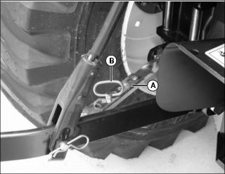
Using 3-Point Hitch
NOTE: The 3-point hitch on your machine is classified as a Category 1 hitch.

· Place center link (A) in storage hook (B) when the hitch is not in use.
Positioning Center Link

Using Rockshaft Control Lever
Use rockshaft control lever (A) to raise and lower equipment attached to the 3-point hitch.
The six calibrated setting are for reference only and do not signify specific operating depths. When the rockshaft control lever is moved forward, the draft arms will lower closer to the ground.
The adjustable depth stop (B) can be adjusted to maintain a particular implement operating depth. To use the depth stop knob:
1. Operate implement for a few minutes to determine the desired operating depth.
2. Loosen the depth stop knob.
3. Move knob against rockshaft control lever.
4. Tighten knob to keep the depth stop in position. Implement will operate in same position each time rockshaft control lever is pushed against the depth stop.
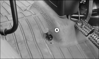
Using Rate of Drop/Lock Valve
IMPORTANT: Avoid damage! To prevent overheating hydraulic oil and damaging machine, do not raise rockshaft when drop/lock valve is closed. |
The rate of drop/lock valve controls the rate of rockshaft drop when the rockshaft control lever is operated. This provides direct rate of drop control for 3-point hitch mounted implements. The valve can also be used to hydraulically lock the rockshaft (three-point hitch) in a desired position.
Picture Note: All controls shown may not be installed on your machine.
Using Draft Links
1. Slowly back machine into position to align draft links with implement lift brackets.
2. Park machine safely. (See Parking Safely in the SAFETY section.)
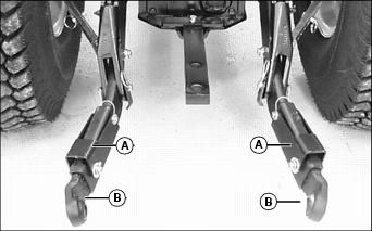
3. For machines equipped with optional telescoping draft links: Raise locking lever (A) and pull link (B) to extend as needed.
4. Connect draft links to the implement.
IMPORTANT: Avoid damage! Telescoping draft link locking levers must be in locked position before operating the machine or link damage could occur. |
5. For machines equipped with optional telescoping draft links:
a. Sit on operator's seat and start engine.
b. Back machine until each lock lever snaps and secures each draft link in the locked position.
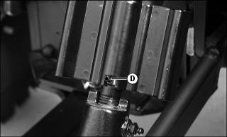
Leveling Implement Front-to-Rear
Leveling a 3-point hitch mounted implement front-to-rear is accomplished by adjusting the length of the center link:
1. Park machine safely. (See Parking Safely in the Safety section.)
3. Rotate handle (B) to lengthen or shorten the center link.
Leveling Implement Side-to-Side

Use turn handle (A) on the right adjustable lift link (B) to level a 3-point hitch implement side-to-side.
1. Park machine safely. (See Parking Safely in the Safety section.)
2. Raise lift link turn handle (A) from transport position and locking tab (C).
3. Rotate handle approximately 1/2 turn. Lower handle notch onto roll pin (D).
4. Rotate handle (A) to raise or lower draft link until 3-point hitch mounted implement is level from side-to-side.
5. Return handle to the transport position with handle notch on locking tab.
Adjusting Implement Side-to-Side Sway
NOTE: Check implement operator's manual procedure for adjusting sway links. When sway links have been properly adjusted, side sway of implement is controlled by position of links.
Use left and right sway links (A) to adjust 3-point hitch implement side-to-side sway:
1. Park machine safely. (See Parking Safely in the SAFETY section.)
3. Slide links to adjust length.
Adjusting Draft Links to Float Position
Adjusting 3-point hitch stops to the float position will allow both draft links to raise slightly as the implement follows ground contour.
Adjust stops to the float position for 3-point hitch implements such as a cultivator or mower. These implements will have ground gauging skids or wheels which may otherwise cause the implement to twist relative to the machine.
1. Park machine safely. (See Parking Safely in the SAFETY section.)
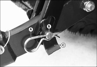
2. Carefully remove spring locking lock pin (A), drilled pin (B) and stop (C) connecting each draft link and lift link.
3. Connect each lift link and draft link with the same hardware making sure the stop (C) is installed in the position shown.
Adjusting Draft Links to Rigid Position
Adjusting 3-point hitch stops to the rigid position will restrict movement of the draft links as the implement follows ground contour.
Adjust stops to the rigid position for 3-point hitch implements such as plows and ground engaging implements that should not twist relative to the machine.
1. Park machine safely. (See Parking Safely in the SAFETY section.)
2. Carefully remove spring locking lock pin (A), drilled pin (B) and stop (C) connecting each draft link and lift link.
3. Connect each lift link and draft link with the same hardware making sure the stop (C) is installed in the position shown.
Using Optional iMatch Quick-Attach Hitch System
The optional quick-attach hitch fits all Category I implements designed to the ASAE Cat I standard for quick-attach hitches.
Installing Hitch
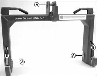
1. Remove three drilled pins (A) and two bushings (B) from quick-attach hitch.
2. Use machine rockshaft control lever to fully lower 3-point hitch draft links.
3. Park machine safely. (See Parking Safely in the SAFETY section.)
4. Position quick-attach hitch near draft links and adjust 3-point hitch sway links to align draft links with quick-attach hitch.
5. Install quick-attach hitch on draft links using drilled pins.
6. Install 3-point hitch center link on quick-attach hitch using center link quick-lock pin and drilled pin.
Connecting Implement
1. Install two bushings included with quick-attach hitch on drilled pins in implement draft link lift brackets.

2. Move levers (A) on quick-attach hitch to unlocked position.
3. Back machine into position and align quick-attach hitch with implement lift brackets.
4. Use rockshaft control lever to position quick-attach hitch under lift brackets and lift implement from ground.

5. Fully raise implement. Move levers (A) on quick-attach hitch to locked position.
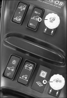
Using Hydraulic Dual Selective Control Valve (SCV)
Implement hydraulic hoses are also color coded. Match the color coded hose ends to the color coded hydraulic couplers on the machine when making connections.
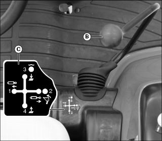
When the implement hydraulic hoses are connected to couplers 3 (black) and 4 (green), move the dual SCV lever (B) rearward to divert fluid to the green connector line and return through the black connector line. Move the lever forward to divert fluid to the black connector line and return through the green connector line. Move the lever to the full forward or "float position" to remove pressure in both connector lines and allow fluid to flow back and forth between the lines.
Refer to information label (C) if further operating assistance is required. See your implement Operator's Manual for implement functions which correspond to lever positions.
IMPORTANT: Avoid damage! To prevent contamination of female quick couplers, color-coded hose ends should be installed in the couplers when not being used. |
Using Dual Selective Control Valve (SCV) Lock Lever
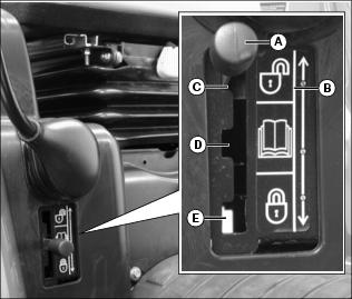
· Move lock lever to the top position (C) to allow dual SCV lever movement in all directions. Operation of the dual SCV is totally unlocked.
· Move lock lever to the middle position (D) to prohibit engagement of the regen (regeneration) function of the dual SCV. This position is recommended for all implements except for the front loader. Heavily-loaded loader buckets will drop more rapidly when the regen function is engaged. Lightly-loaded loader buckets will not benefit from use of the regen function. The regen function is available only with the lock lever in position C.
· Move lock lever to the bottom position (E) to prohibit dual SCV lever movement in all directions. Operation of the dual SCV is totally locked.
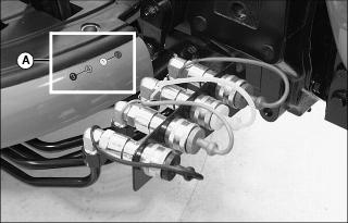
Using Hydraulic Third Selective Control Valve (SCV)
This machine model series can be equipped with an optional hydraulic third Selective Control Valve (SCV) and hydraulic outlets to operate hydraulically-driven implements.
The machine-mounted hydraulic outlets are female quick couplers.

When the implement hydraulic hoses are connected to the couplers, move the third SCV lever (A) forward to divert fluid to the lower connector line and return through the upper connector line. Move the lever rearward to divert fluid to the upper connector line and return through the lower connector line. Move the lever to the full forward or "float position" to remove pressure in both connector lines and allow fluid to flow back and forth between the lines.
Refer to the information label (B) if further operating assistance is required. See your implement Operator's Manual for implement functions which correspond to lever positions.
IMPORTANT: Avoid damage! To prevent contamination of female quick couplers, hose ends should be installed in the couplers when not being used. |
Connecting Implement Hydraulic Hoses
1. Park machine safely. (See Parking Safely in the SAFETY section.)
2. Relieve hydraulic pressure:
· Move dual SCV lever (A) rearward-to-forward and side-to-side several times.
· Move third SCV lever (B) rearward-to-forward several times.
3. Refer to implement operator's manual for instructions on connecting hydraulic hoses to couplers.
Ballasting Machine
Add weight to machine front end if needed for stability. Heavy pulling and heavy rear mounted implements tend to lift front wheels. Add enough ballast to maintain steering control and prevent tip over. Remove weight when it is no longer needed.
Implement Codes
Use the following tables to determine the number of front weights to use with John Deere implements that show implement code data in the ballasting section of the implement operator's manual.
Match the implement code from the implement manual with the codes for your machine and type of hitch. If the code falls between two numbers in the table, use the next higher number in the table for the number of front weights to use with that implement.
These codes are for ideal conditions. Actual field conditions may require additional ballast. Some John Deere implements may recommend using a certain number of front weights rather than giving implement codes.
Tire Capacities
Use the following charts to determine the tire maximum inflation pressure and load capacity.
Verify maximum tire inflation pressure and maximum load information if embossed into the tire side wall.
* Maximum pressure following tire manufacturer's specifications.
**Maximum load capacity for single tire.
* Maximum pressure following tire manufacturer's specifications.
**Maximum load capacity for single tire.
Using Optional Rear Cast Iron Wheel Weights
IMPORTANT: Avoid damage! Do not overload tires. Do not exceed tire maximum inflation pressure or maximum load capacity. |
1. Mount rear wheels in the wide position for improved stability.
2. Fasten weight to each rear wheel using a safe lifting device. A total of three weights per wheel may be used. See your implement operator's manual for installation and number of weights to use.
Rear wheel weights are available from your John Deere Dealer.
Using Optional Rear Ballast Box
IMPORTANT: Avoid damage! Do not overload tires. Do not exceed tire maximum inflation pressure or maximum load capacity. |
The rear ballast box is used for carrying ballast on the 3-point hitch. Approximate weight of different materials is given in the implement operator's manual.
Using Liquid Weight in Tires
NOTE: Use of alcohol as ballast is not recommended. Calcium chloride solution is heavier and more economical.
A solution of water and calcium chloride provides safe economical ballast, and will prevent freezing. If used properly, it will not damage tires, tubes, or rims.
A mixture of 0.4 kg of calcium chloride per liter of water (3.5 lb/gal), will not freeze solid above -45° C (-50° F).
Fill tubeless tires at least to valve stem level (minimum 75% full). Less solution would expose part of rim, possibly causing corrosion.
Tube-type tires may be filled to any level below 90%.
Using Optional Front Weights
Front weight bracket (A) is an integral part of the machine frame. The bracket will hold up to six Quick-Tatch® weights.
Quick-Tatch weights and attaching hardware are available at your John Deere dealer.
See your implement operator's manual for installation and required number of weights to use.
An optional front weight bracket extension kit is available at your John Deere dealer. This optional front weight bracket extension kit will hold up to six additional Quick-Tatch weights.
Transporting Machine on Trailer
NOTE: Use a heavy-duty trailer to transport your machine.
1. Drive machine forward onto trailer.
2. Lower any implements to trailer deck.
6. Close the fuel shut-off valve.
7. Fasten machine to trailer with heavy-duty straps, chains, or cables. Both front and rear straps must be directed down and outward from machine. Trailer must have signs and lights as required by law.
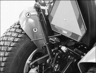
Transporting Machine
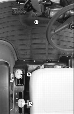
Driving Machine Safely on Roads
Observe the following precautions when operating the machine on a road:
· Make sure brake pedals are locked together with the brake pedal latch.
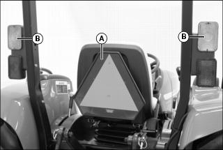
· Make sure SMV (Slow Moving Vehicle) emblem (A) and warning lights (B) are clean and visible. If towed or rear-mounted equipment obstructs these safety devices, install SMV emblem and warning lights on equipment.

· Rotate light switch (C) to road position (D).
· Drive slowly enough to maintain safe control at all times. Slow down for hillsides, rough ground, and sharp turns, especially when transporting heavy, rear-mounted implements.
· Adjust tread width position of rear wheels to provide maximum stability.
· If equipped, disengage the MFWD to reduce tire wear.
· Never coast machine downhill.
Pushing or Towing Machine
IMPORTANT: Avoid damage! Push or tow machine for short distances only. MFWD remains engaged on eHydro and ePowrReverser models when the engine is turned off. |
1. Push the rear and mid-PTO knobs to the disengaged/off position.
2. Disengage the differential lock.
4. Move transmission to neutral position:
· All gear models: Depress clutch pedal completely and move the transmission gear and range shift levers to the N (neutral) position.
· ePowrReverser model: move the reverser lever to neutral position.
· eHydro model: move the range shift lever to the N (neutral) position.
5. If equipped, disengage the MFWD.
6. Make sure brake pedals are locked together with the brake pedal latch to slow or stop machine.
Towing Loads
1. Hitch the towed load only to the drawbar. Lock the drawbar and pin in place.
2. Install a safety chain to the machine drawbar support and to the towed load. Provide only enough slack to permit turning.
3. Gear Models: Before descending a hill, shift to a gear low enough to control machine travel speed without having to use the brake pedals to brake the machine and installed implements.
Using Safety Chain

1. Use the appropriate adapter parts (A) to attach the safety chain to the machine drawbar support and to the towed load. Provide only enough slack to permit turning.
2. Install additional attaching points (B) for the chain on drawbar to reduce slack in chain when necessary.
3. Remove the safety chain and store when not in use.
Raising and Lowering Roll-Over Protective Structure (ROPS)
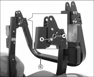
Lowering ROPS Crossbar
1. Remove spring locking pin (A) and drilled pin (B) on each side of the ROPS.
2. Carefully lower ROPS crossbar (C).

3. Align crossbar bracket holes with support bracket holes on each side of the ROPS.
4. Install drilled pins (B) and spring locking pins (A) to lock crossbar (C) in the lowered position.
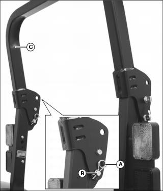
Raising ROPS Crossbar
1. Remove spring locking pins (A) and drilled pins (B) on each side of the ROPS.
2. Carefully raise ROPS crossbar (C) to the operating position.

3. Align crossbar bracket holes with support bracket holes on each side of the ROPS.
4. Install drilled pins (B) and spring locking pins (A) to lock crossbar (C) in the raised position.