
Service Miscellaneous
Filling Fuel Tank
Use diesel fuel Grade No. 1-D for cold air temperatures or Grade No. 2-D fuel for warm air temperatures. Diesel fuel must be cetane Number 40. A cetane number of 50 or more is preferred, especially for air temperatures below -20°C (-4°F) or elevations above 1500 m (5000 ft).
Number 2 or better diesel fuel is recommended. Using other fuel will result in increased fuel consumption and decreased engine performance.
Add John Deere fuel stabilizer to fuel before using it in your machine to prevent engine damage due to stale fuel. Follow directions on stabilizer container.
1. Park machine safely. (See Park Safely in SAFETY section.)
2. Allow engine to cool several minutes before you add fuel.
3. Remove grass clippings and other trash from tank area.
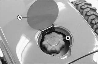
6. Fill tank with fresh fuel only to bottom of filler neck.
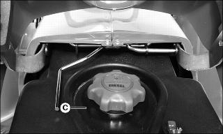
· If fuel is spilled, raise hood and clean overfill reservoir (C).
Tightening Wheel Hardware
When machine is new or anytime wheel hardware is loosened, tighten all bolts after one hour of operation and every four hours thereafter until proper torque values are maintained.
Tightness of wheel hardware must be maintained according to service interval recommendations. Check wheel bolt tightness as follows:
Front Wheel Bolts
Tighten front wheel disk-to-flange bolts alternately to 155 N·m (114 lb-ft).
Rear Wheel Bolts
Tighten rear wheel disk-to-flange bolts alternately to 155 N·m (114 lb-ft).
Selecting Front Tire Rolling Direction
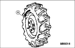
Machines equipped with directional type tires (such as bar tires) have directional arrows (A) located on the tire sidewall. Under most conditions, tires should be installed with the directional arrow pointing in the direction of travel.
If machine is mainly used for loader operations, lug direction may be reversed to increase tire life and improve traction while backing out of dirt piles.
Move wheel from one side of machine to the other.
Changing Wheel Spacing and Tread Width
The front and rear wheels can be mounted in wide or narrow positions to increase or decrease wheel spacing. To provide best stability, operate machine with rear wheels mounted in the wide tread position whenever possible.
Front Wheel Positions:
· Wide position - Install wheel with valve stem to the inside.
· Narrow position - Install wheel with valve stem to the outside.
Rear Wheel Positions:
· Wide position - Install wheel with valve stem to the outside.
· Narrow position - Install wheel with valve stem to the inside.
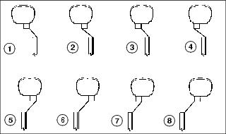
The mounting flanges on the rear rims are closer to one edge of the rim than the other, allowing the inner wheels to be mounted in different positions. By changing this position of the wheel on the rim, up to eight different tread widths can be achieved on some machines.
Various positions cannot be used because the tires would strike the fenders. Certain other positions may result in equal tread widths.
The front wheel spacing can be adjusted to eight different tread widths by reversing the front wheels and by extending the front axle.
Tread width is measured from centerline-to-centerline of each tire.
Mounting Guidelines
· To keep tire rotation in the proper direction when wheels are reversed without removing tires from rims, move each wheel to the opposite side of the machine.
· Rims can be attached to either side of wheel.
· Mounting flanges on rim are closer to one edge of rim.
· Tread width can be changed by turning the wider side in or out.
· To keep tire rotation in the proper direction, move each rim to opposite side of machine, rather than turning the rims around.
· Dished wheels can be reversed.
· Tighten all bolts to specifications.
Rear Tire Tread Width Dimensions
Front Tire Tread Width Dimensions (2WD Tractors)
Front Tire Tread Width Dimensions (MFWD Tractors)
Adjusting Front Axle Width (2WD Models)
Adjust front axle width as needed to achieve desired front tire tread width.
1. Park machine safely. (See Parking Safely in the SAFETY section.)
2. Raise front of machine with a safe lifting device. Support with blocks and/or jack stands.
3. Loosen tie rod tube jam nuts (A) and bolts (B) on each side of the front axle. Do not remove bolts.
4. Remove two hex lock nuts (C) and two axle bolts from each side of the front axle.
NOTE: Tie rod and power steering cylinder will self-align to the proper width position as axle is extended.
5. Pull outward on each wheel assembly to extend the inner axle channel to the desired width. Holes must align with holes in inner axle channel.
6. Install axle bolts and lock nuts (C). Tighten bolts to 260 N·m (190 lb-ft).
7. Tighten bolts (B) to 79-98 N·m (58-72 lb-ft).
10. Check toe-in setting. Adjust if needed.
Checking and Adjusting Toe-In
1. Stop machine on a firm, level surface.
2. Disengage MFWD if equipped.
3. Turn steering wheel so front wheels are pointing straight ahead.
4. Park machine safely. (See Parking Safely in the SAFETY section.)
Checking Toe-In
NOTE: If front axle is equipped with bar tires, use an outside bar of each tire or an inside bar of each tire for marking the center line.
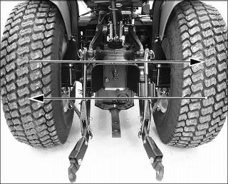
1. Mark the center line of each tire at hub height and to the front of the axle using chalk.
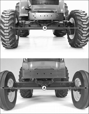
Picture Note: Top photo shows a MFWD model machine. Bottom photo shows a 2WD model machine.
2. Measure distance (A) between the center lines of each tire. Record the measurement.
3. Drive machine forward or rearward slightly until chalk mark moves 180° to the rear of the axle.
4. Park machine safely. (See Parking Safely in the SAFETY section.)
5. Measure distance (A) again between the chalk marks. Record the measurement.
6. Determine the difference between front and rear measurements:
· 2WD Machines - Distance (A) at front of tires should be 3 - 6 mm (1/8 - 1/4 in.) less than distance at rear of tires. If not, adjust toe-in.
· MFWD Machines - Distance (A) may be larger at front or rear measurement but should not exceed 3 mm (1/8 in.). Adjust toe-in if necessary.
Adjusting Toe-In (MFWD Models)
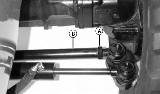
1. Loosen jam nuts (A) on both tie rods.
2. Rotate tie rods (B) clockwise or counterclockwise to adjust the amount of toe-in. Adjust tie rods until toe-in measurement is within correct specification.
· Rotating threaded rod in 1/2 turn increments equals 1.5mm (1/16 in.).
3. Tighten jam nuts (A) to 120 N·m (88 lb-ft).
4. Check toe-in setting. Repeat procedure if further adjustment is required.
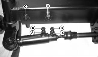
Adjusting Toe-In (2WD Models)
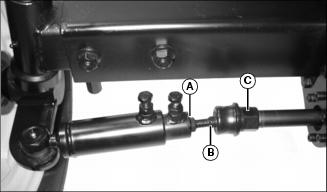
1. Loosen jam nut (A) on each side of the front axle.
2. Rotate adjuster (B) while holding hex nut (C) to lengthen or shorten each tie rod. Adjust each tie rod equally until toe-in measurement is within correct specification.
· Rotating threaded rod in 1/2 turn increments equals 1.5mm (1/16 in.).
3. Tighten jam nuts (A) to 120 N·m (88 lb-ft).
4. Check toe-in setting. Repeat procedure if further adjustment is required.
Tightening Front Axle Hardware (2WD Models)
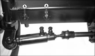
· Tighten front axle bolts (A) to 260 N·m (190 lb-ft).
Cleaning and Repairing Plastic Surfaces
Your John Deere dealer has the professional materials needed to properly remove surface scratches from any plastic surfaces, do not attempt to paint over marks or scratches in plastic parts.
1. Rinse hood and entire machine with clean water to remove dirt and dust that may scratch the surface.
2. Wash surface with clean water and a mild liquid automotive washing soap.
3. Dry thoroughly to avoid water spots.
4. Wax the surface with a liquid automotive wax. Use products that specifically say "contains no abrasives."
5. Buff applied wax by hand using a clean, soft cloth.
Cleaning and Repairing Metal Surfaces
Cleaning:
Follow automotive practices to care for your machine painted metal surfaces. Use a high-quality automotive wax regularly to maintain the factory look of your machine's painted surfaces.
Repairing Minor Scratches (surface scratch):
1. Clean area to be repaired thoroughly.
2. Use automotive polishing compound to remove surface scratches.
3. Apply wax to entire surface.
Repairing Deep Scratches (bare metal or primer showing):
1. Clean area to be repaired with rubbing alcohol or mineral spirits.
2. Use paint stick with factory-matched colors available from your John Deere dealer to fill scratches. Follow directions included on paint stick for use and for drying.
3. Smooth out surface using an automotive polishing compound. Do not use power buffer.
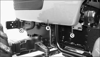
Raising and Lowering Hood
Raising
1. Park machine safely. (See Parking Safely in the SAFETY section.)
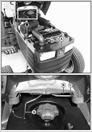
2. Depress hood release button (A).
3. Raise hood until latch support rod (B) engages bracket hole (C).
Lowering
1. Lift hood slightly to remove weight from latch support rod.
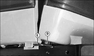
2. Push latch release rod (D) outward to release support rod.
4. Push down on front of hood to lock the latch.
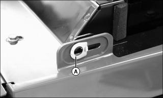
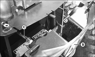
Removing and Installing Engine Side Panels
Removing
1. Park machine safely. (See Parking Safely in the SAFETY section.)
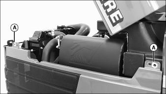
3. Flip up and turn each spring loaded fastener (A) to the horizontal position.
4. Lift each side panel (B) off the two lower rod supports (C) to remove.
Installing
1. Install bottom of each side panel onto the two lower rod supports.
2. Install fasteners (A) through slots at the top of each panel. Turn each fastener vertical and flip down to secure panel in position.
Removing and Installing Front Grille
Removing
1. Park machine safely. (See Parking Safely in the SAFETY section.)
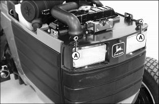
3. Flip up and turn spring loaded fasteners (A) to the horizontal position.
4. Carefully move top of grille (B) forward.
5. Disconnect wire harness (C) from each headlight assembly.
6. Lift grille so alignment tabs (D) are out of the rod supports (E) and remove.
Installing
1. Connect wire harness (C) to each headlight assembly.
2. Install alignment tabs at bottom of grill into each rod support.
3. Carefully move top of grille rearward.
4. Install fasteners through slots at top of grille. Turn each fastener vertical and flip down to secure grille in position.