
Service Engine
Engine Warranty Maintenance Statement
Maintenance, repair, or replacement of the emission control devices and systems on this engine, which are being done at the customers expense, may be performed by any non-road engine repair establishment or individual. Warranty repairs must be performed by an authorized John Deere dealer.
Avoid Fumes
Engine Oil
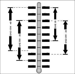
Use oil viscosity based on the expected air temperature range during the period between oil changes.
The following John Deere oils are preferred:
Other oils may be used if above John Deere oils are not available, provided they meet the following specification:
· API Service Classification SG or higher
Checking Engine Speeds
Check engine speeds when engine is warmed up and not under load.
Observe tachometer.
· Slow idle (no load)................................... 1050 rpm
· Fast idle (no load).....................................2800 rpm
If above engine speeds are not to specifications, see your John Deere dealer.
Checking Engine Oil Level
NOTE: Check oil twice a day if you run engine over 4 hours in a day.
Make sure engine is cold when checking engine oil level.
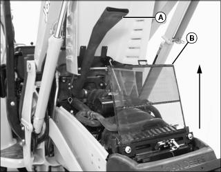
1. Raise front loader boom and install loader boom service lock. (See Using Loader Boom Service Lock in the SAFETY section.)
2. Park the machine safely for service. (See Parking Safely in the SAFETY section.)
IMPORTANT: Avoid damage! Dirt and contamination can enter engine when checking oil level. Clean area around dipstick before removing. |
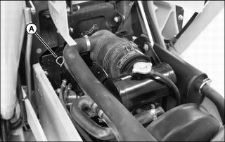
4. Remove dipstick (A). Wipe with a clean cloth.
7. Check oil level on dipstick; oil level should be between FULL and ADD levels on dipstick.
a. Remove side panel on right side of engine.
c. Add proper engine oil until oil level is within operating range on dipstick. Do not overfill.
10. If oil is above FULL level on the dipstick, drain to proper level.
Changing Engine Oil and Filter
1. Run engine to warm the oil.
2. Raise front loader boom and install loader boom service lock. (See Using Loader Boom Service Lock in the SAFETY section.)
3. Park the machine safely for service. (See Parking Safely in the SAFETY section.)
5. Place container under oil drain located on right side of engine.
6. Remove side panel on right side of engine.
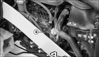
8. Wipe dirt from around oil filter (B).
9. Turn filter counter-clockwise to remove.
10. Put a light coat of clean engine oil on the gasket of new filter.
11. Install replacement oil filter by turning filter clockwise until gasket contacts filter base. Tighten additional one-half turn.
12. Install drain plug. Do not overtighten.
· Engine oil capacity is 4.9 L (5 qt).
16. Start and run engine at idle to check for leaks.
17. Stop engine. Fix any leaks before operating.
18. Check engine oil level, add oil if necessary.
Cleaning Air Filter Dust Unloading Valve
IMPORTANT: Avoid damage! Prevent damage to the engine. Never operate engine without air cleaner elements and rubber dust unloading valve installed. |
1. Raise front loader boom and install loader boom service lock. (See Using Loader Boom Service Lock in the SAFETY section.)
2. Park the machine safely for service. (See Parking Safely in the SAFETY section.)
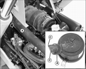
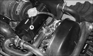
4. Locate dust unloading valve (A) attached to the front of the air cleaner canister (B).
NOTE: The air cleaner canister cover is removed to illustrate photo clarity only. Removal of the canister cover or dust unloading valve is not required.
5. Pinch corners (C) to allow any dirt or debris to fall out of the valve.
Servicing Air Cleaner Element
IMPORTANT: Avoid damage! Dirt and debris can enter the engine when removing the filter element. Service filter elements only when indicator light on the instrument panel is illuminated. |
Checking Primary Air Filter Element
1. Start engine. Allow engine to run approximately one minute at maximum throttle speed.
2. Check air restriction indicator light on instrument panel:
· If indicator light remains off, no air cleaner service is required.
· If indicator light is illuminated, air cleaner requires immediate service.
Servicing Primary Air Filter Element:
1. Raise front loader boom and install loader boom service lock. (See Using Loader Boom Service Lock in the SAFETY section.)
2. Park the machine safely for service. (See Parking Safely in the SAFETY section.)
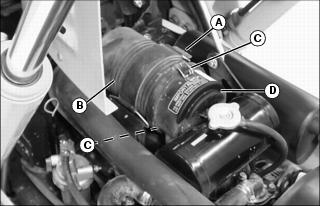
5. Release strap (A) securing air cleaner canister (B).
6. Raise front of air cleaner canister slightly.
7. Release latches (C) and remove air cleaner canister cover (D).
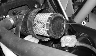
8. Remove and discard primary element (E). Replace with a new primary filter element.
9. Install air cleaner canister cover (D) with rubber dust unloading valve pointing downward.
10. Check instruction molded into canister cover for proper installation.
11. Hook latches (C) onto cover.
12. Lower front of air cleaner canister and install strap (A).
13. Start engine. Allow engine to run approximately one minute at maximum throttle speed.
14. Check air restriction indicator light on instrument panel.
· If indicator light remains off, no air cleaner service is required.
· If indicator light is illuminated, air cleaner requires immediate service.
Servicing Secondary Air Filter Element:
NOTE: This service procedure should be completed only if the primary air filter element has been replaced and the air restriction indicator light remains illuminated.
1. Remove air cleaner canister cover.
2. Remove primary air filter element.
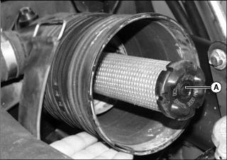
3. Remove and discard secondary air filter element (A). Replace with a new secondary air filter element.
4. Install primary air filter element.
5. Replace air cleaner canister cover.
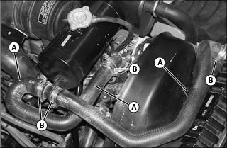
Checking Air Filter Intake Hoses and Clamps
1. Raise front loader boom and install loader boom service lock. (See Using Loader Boom Service Lock in the SAFETY section.)
2. Park the machine safely for service. (See Parking Safely in the SAFETY section.)
4. Remove side panel from right side of engine.
5. Check hoses for damage or cracking. Replace if necessary.
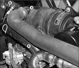
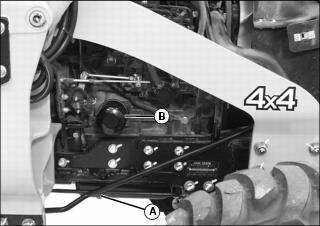
6. Tighten upper air intake hose clamp (A).
7. Tighten lower air intake hose clamps (B).
Service Cooling System Safely
Recommended Engine Coolant
The following John Deere coolants are preferred:
· COOL-GARD® PRE-DILUTED SUMMER COOLANT (TY16036).
· COOL-GARD® CONCENTRATED SUMMER COOLANT (TY16034).
If neither of the recommended coolants is available, use a glycol base coolant that meets the following specification:
Check container label before using to be sure it has the appropriate specifications for your machine. Use coolant with conditioner or add conditioner to coolant before using.
If using concentrate, mix approximately 50 percent antifreeze with 50 percent distilled or deionized water before adding to cooling system. This mixture will provide freeze protection to -37 degrees C (-34 degrees F).
Certain geographical areas may require lower temperature protection. See the label on your antifreeze container or consult your John Deere dealer to obtain the latest information and recommendations. Never exceed the maximum dilution rate for the coolant you are using. Exceeding the maximum rate will greatly reduce the coolant effectiveness.
Servicing Cooling System
Checking Radiator Coolant Level
1. Raise front loader boom and install loader boom service lock. (See Using Loader Boom Service Lock in the SAFETY section.)
2. Park the machine safely for service. (See Parking Safely in the SAFETY section.)
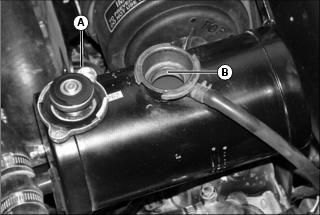
5. Remove recovery tank cap (A).
6. Check recovery tank coolant level:
· If engine is warm, coolant level should be approximately 10 mm (0.40 in.) below bottom of filler neck (B).
· If engine is cold, coolant level should be approximately 30 mm (1.2 in.) below bottom of filler neck (B).
7. Add pre-diluted coolant or specified ratio of antifreeze and water.
8. Install and tighten recovery tank cap.
Draining Cooling System
1. Raise front loader boom and install loader boom service lock. (See Using Loader Boom Service Lock in the SAFETY section.)
2. Park the machine safely for service. (See Parking Safely in the SAFETY section.)
5. Remove side panel on right side of engine.
6. Slowly open recovery tank cap (A) to the first stop to release all pressure.
7. Open radiator petcock (B). Drain coolant into a pan.
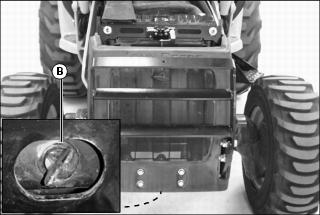
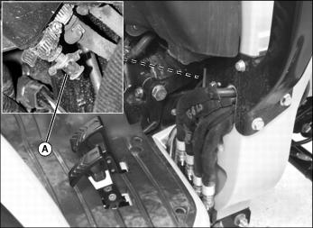
Picture Note: Engine block drain plug is located behind the engine mounting plate.
8. Position drain pan under engine block drain plug (C) at right side of engine. Remove drain plug and allow all coolant to drain.
9. Close radiator petcock and install engine block drain plug.
Flushing Cooling System
1. Fill cooling system with clean water and John Deere Cooling System Cleaner, or John Deere Cooling System Quick Flush or an equivalent. Follow directions on the can.
2. Install and tighten radiator cap.
3. Start and run engine until it reaches operating temperature.
5. Open radiator petcock and remove engine block drain plug.
6. Drain cooling system immediately before rust and dirt settle.
7. Close radiator petcock and install engine block drain plug.
Filling Cooling System
NOTE: John Deere COOL-GARD coolant is recommended when adding new coolant to the cooling system.
Follow the directions on the container for correct mixture ratio.
· Cooling system capacity is 8.7 L (2.3 gal).
3. Install and tighten radiator cap.
4. Run engine until it reaches operating temperature.
8. Check recovery tank coolant level:
· If engine is warm, coolant level should be approximately 10.0 mm (0.40 in.) below bottom of filler neck.
· If engine is cold, coolant level should be approximately 30.0 mm (1.2 in.) below bottom of filler neck.
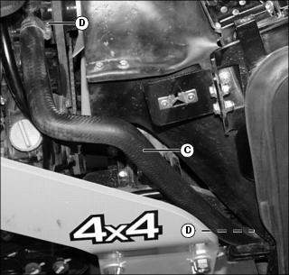
Checking Radiator Hoses and Clamps
1. Raise front loader boom and install loader boom service lock. (See Using Loader Boom Service Lock in the SAFETY section.)
2. Park the machine safely for service. (See Parking Safely in the SAFETY section.)
4. Remove both engine side panels.
5. Check upper radiator hose (A) for damage or cracking. Replace if necessary.
6. Tighten hose clamps (B) as needed.
7. Check lower radiator hose (C) for damage or cracking. Replace if necessary.
8. Tighten hose clamps (D) as needed.
Servicing the Alternator Belt
Checking Belt Tension
1. Raise front loader boom and install loader boom service lock. (See Using Loader Boom Service Lock in the SAFETY section.)
2. Park the machine safely for service. (See Parking Safely in the SAFETY section.)
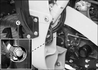
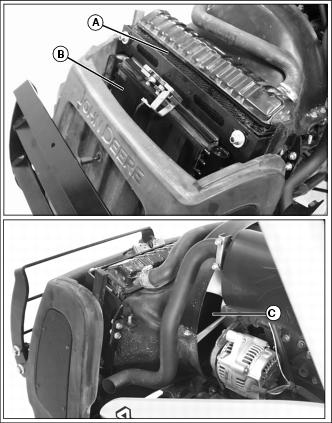
4. Remove side panel from left side of engine.
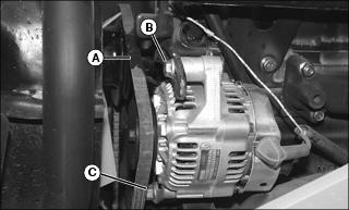
5. Apply moderate thumb pressure to belt (A) halfway between the pulleys. Belt should deflect inward approximately 9 mm (3/8 in.).
6. Adjust belt tension if deflection is more or less than specified.
Adjusting Belt Tension
3. Apply outward pressure to alternator housing until tension is correct.
Replacing Belt
NOTE: Replace alternator belt if excessive wear, damage or stretching is detected.
1. Disconnect black negative (-) cable from battery.
3. Remove both engine side panels.
IMPORTANT: Avoid damage! Do not loosen or remove the pump mounting or pump plate mounting bolts. The pump will move out of alignment which will damage the pump and coupler. |
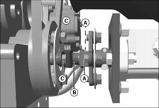
4. Remove two capscrews (A) and nuts securing center connector (B) to the pump shaft coupler.
5. Remove two capscrews (C) securing center connector (B) to the crankshaft sheave.
6. Remove center connector (B).
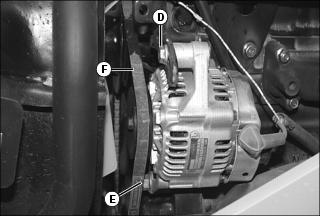
9. Apply inward pressure to alternator housing.
10. Remove belt (F) from alternator sheave, fan sheave and crankshaft sheave.
11. Route defective belt over fan and remove.
12. Install new belt over fan and onto sheaves.
13. Apply outward pressure to alternator housing until tension is correct.
14. Tighten bolts (D) and (E).
15. Check belt tension. Adjust as necessary.
16. Install pump center connector (B).
17. Apply medium strength thread-locking adhesive to the threads of capscrews (C).
18. Install capscrews (C) into the crankshaft sheave. Tighten to 18 N·m (13.3 lb-ft).
19. Apply medium strength thread-locking adhesive to the threads of capscrews (A).
20. Install capscrews (A) and nuts to the pump shaft coupler. Tighten to 18 N·m (13.3 lb-ft).
21. Connect black negative (-) cable to battery.
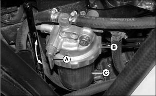
Checking Fuel Filter Sediment Bowl
1. Raise front loader boom and install loader boom service lock. (See Using Loader Boom Service Lock in the SAFETY section.)
2. Park the machine safely for service. (See Parking Safely in the SAFETY section.)
5. Remove side panel from right side of engine.
NOTE: Red ring in bottom of sediment bowl will float on water. If ring is floating, sediment bowl should be cleaned.
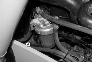
6. Check for water and deposits in sediment bowl (A).
7. Clean sediment bowl and replace fuel filter if necessary.
Cleaning Fuel Filter Sediment Bowl and Replacing Filter
NOTE: Change filter when fuel is low.
1. Raise front loader boom and install loader boom service lock. (See Using Loader Boom Service Lock in the SAFETY section.)
2. Park the machine safely for service. (See Parking Safely in the SAFETY section.)
4. Remove side panel from right side of engine.
5. Close fuel shut-off valve (A).
6. Position drain pan under fuel filter sediment bowl to catch fuel spillage.
7. Turn locking collar (B) counterclockwise to remove bowl (C).
8. Remove and discard the fuel filter.
9. Remove and retain the plastic ring and spring from sediment bowl.
10. Clean bowl, plastic ring, and spring.
11. Install plastic ring and spring in original position in sediment bowl.
12. Install new filter to filter head.
13. Place sediment bowl and locking collar in position.
14. Tighten locking collar to filter head to secure.
NOTE: Fuel system is self bleeding.
18. Crank engine to bleed fuel system.
Fuel Injection Pump
IMPORTANT: Avoid damage! Do not clean a warm or hot fuel injection pump with steam or water. Clean with compressed air if pump is not cooled. |
NOTE: The fuel injection pump is calibrated by the engine manufacturer and should not require any adjustments.
If engine is hard to start, lacks power, or runs rough, see Troubleshooting Section of this manual.
After performing the checks in the troubleshooting section, if your engine is still not performing correctly, contact your John Deere dealer.
Fuel Injection Nozzles
If injection nozzles are not working correctly or are dirty, engine will run poorly. See your John Deere dealer for service.
Draining Water and Sediment From Fuel Tank
1. Raise front loader boom and install loader boom service lock. (See Using Loader Boom Service Lock in the SAFETY section.)
2. Park the machine safely for service. (See Parking Safely in the SAFETY section.)
3. Locate petcock drain (A) in front of the travel pedals on the right side of the machine.
4. Open petcock drain. Drain accumulated moisture and sediment from the fuel tank into a small container.
5. Close drain when fuel flow is clear.
Cleaning Grille and Side Screens
IMPORTANT: Avoid damage! Grille and side panel screens must be clean to prevent engine from overheating and to allow adequate air intake. |
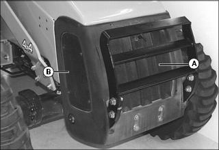
1. Check grille (A) and both side panel screens (B) for dirt and debris.
2. Clean dirty grille and side screens with a brush or cloth.
Inspecting Foam Air Blocks
IMPORTANT: Avoid damage! Foam air blocks must be in place to prevent engine and hydraulic oil from overheating and to allow adequate air intake. |
1. Raise front loader boom and install loader boom service lock. (See Using Loader Boom Service Lock in the SAFETY section.)
2. Park the machine safely for service. (See Parking Safely in the SAFETY section.)
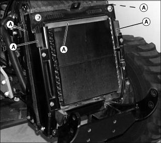
Picture Note: Grille assembly removed for clarity.
4. Check that foam air blocks (A) around radiator are in place and not damaged.
5. Check that foam air block on hood (not shown) is in place and not damaged.
Cleaning Radiator Cooling Screen, Radiator Cooling Fins and Oil Cooler Fins
· Clear work area of bystanders. · Wear eye protection when using compressed air for cleaning purposes. |
IMPORTANT: Avoid damage! The radiator cooling screen must be clean to prevent engine from overheating and to allow adequate air intake. |
Cleaning Radiator Cooling Screen
1. Raise front loader boom and install loader boom service lock. (See Using Loader Boom Service Lock in the SAFETY section.)
2. Park the machine safely for service. (See Parking Safely in the SAFETY section.)
5. Lift and remove radiator screen (B).
6. Clean screen with compressed air, brush or cloth.
7. Check radiator fins and oil cooler fins for dirt and debris. If necessary, clean fins.
Cleaning Radiator Cooling Fins and Oil Cooler Fins
NOTE: The radiator cooling fins and oil cooler fins may become extremely dirty or plugged when operating in severe conditions. If necessary, remove attaching hardware and upper half of fan shroud to thoroughly clean the fins.
2. Remove all dirt and debris from radiator fins (A), oil cooler fins (B) and area (C) inside the fan shroud using compressed air or water.