
Service Miscellaneous
Filling Fuel Tank
Use diesel fuel Grade No. 1-D for cold air temperatures or Grade No. 2-D fuel for warm air temperatures. Diesel fuel must be cetane Number 40. A cetane number of 50 or more is preferred, especially for air temperatures below -20°C (-4°F) or elevations above 1500 m (5000 ft).
Number 2 or better diesel fuel is recommended. Using other fuel will result in increased fuel consumption and decreased engine performance.
Add John Deere fuel stabilizer to fuel before using it in your machine to prevent engine damage due to stale fuel. Follow directions on stabilizer container.
1. Park machine safely. (See Park Safely in SAFETY section.)
2. Allow engine to cool several minutes before you add fuel.
3. Remove dirt, debris, and other trash from tank area.
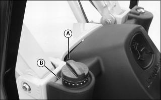
5. Fill tank with fresh fuel only to bottom of filler neck.
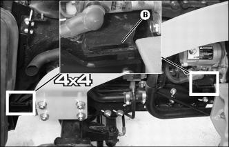
· If fuel is spilled, clean splash area (B).
Tightening Wheel Hardware
When machine is new or anytime wheel hardware is loosened, tighten all bolts after one hour of operation and every four hours thereafter until proper torque values are maintained.
Tightness of wheel hardware must be maintained according to service interval recommendations. Check wheel bolt tightness as follows:
Front Wheel Bolts
Tighten front wheel disk-to-flange bolts alternately to 140 N·m (103 lb-ft).
Rear Wheel Bolts
Tighten rear wheel disk-to-flange bolts alternately to 140 N·m (103 lb-ft).
Checking and Adjusting Toe-In
1. Stop machine on a firm, level surface.
3. Turn steering wheel so front wheels are pointing straight ahead.
4. Park machine safely. (See Parking Safely in the SAFETY section.)
Checking Toe-In
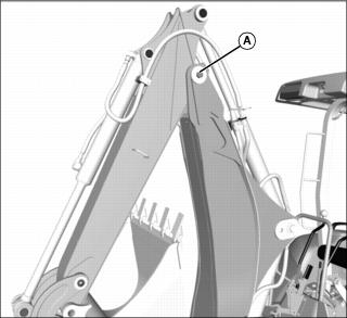
1. Mark the center line of each tire at hub height and to the front of the axle using chalk.
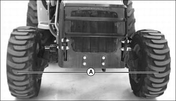
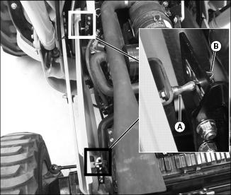
2. Measure distance (A) between the center lines of each tire. Record the measurement.
3. Drive machine forward or rearward slightly until chalk mark moves 180° to the rear of the axle.
4. Park machine safely. (See Parking Safely in the SAFETY section.)
5. Measure distance (A) again between the chalk marks. Record the measurement.
6. Determine the difference between front and rear measurements:
· Distance (A) may be larger at front or rear measurement but should not exceed 3 mm (1/8 in.). Adjust toe-in if necessary.
Adjusting Toe-In
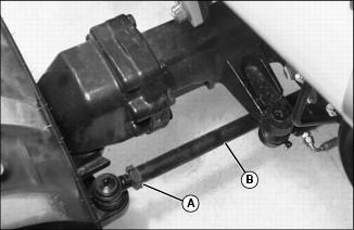
1. Loosen jam nuts (A) on both ends of tie rod.
2. Rotate tie rod (B) clockwise or counterclockwise to adjust the amount of toe-in. Adjust tie rod until toe-in measurement is within correct specification.
· Rotating threaded rod in 1/2 turn increments equals 1.5mm (1/16 in.).
3. Tighten jam nuts (A) to 120 N·m (88 lb-ft).
4. Check toe-in setting. Repeat procedure if further adjustment is required.
Selecting Tire Rolling Direction
Machines equipped with directional type tires (such as bar tires) have directional arrows located on the tire sidewall. Tires should be installed with the directional arrow pointing in the direction of travel.
Cleaning and Repairing Plastic Surfaces
Your John Deere dealer has the professional materials needed to properly remove surface scratches from any plastic surfaces, do not attempt to paint over marks or scratches in plastic parts.
1. Rinse hood and entire machine with clean water to remove dirt and dust that may scratch the surface.
2. Wash surface with clean water and a mild liquid automotive washing soap.
3. Dry thoroughly to avoid water spots.
4. Wax the surface with a liquid automotive wax. Use products that specifically say "contains no abrasives."
5. Buff applied wax by hand using a clean, soft cloth.
Cleaning and Repairing Metal Surfaces
Cleaning:
Follow automotive practices to care for your machine painted metal surfaces. Use a high-quality automotive wax regularly to maintain the factory look of your machine's painted surfaces.
Repairing Minor Scratches (surface scratch):
1. Clean area to be repaired thoroughly.
2. Use automotive polishing compound to remove surface scratches.
3. Apply wax to entire surface.
Repairing Deep Scratches (bare metal or primer showing):
1. Clean area to be repaired with rubbing alcohol or mineral spirits.
2. Use paint stick with factory-matched colors available from your John Deere dealer to fill scratches. Follow directions included on paint stick for use and for drying.
3. Smooth out surface using an automotive polishing compound. Do not use power buffer.
Raising and Lowering Hood
Raising
1. Raise front loader boom and install loader boom service lock. (See Using Loader Boom Service Lock in the SAFETY section.)
2. Park the machine safely for service. (See Parking Safely in the SAFETY section.)
3. Grasp and pull hood release handle (A).
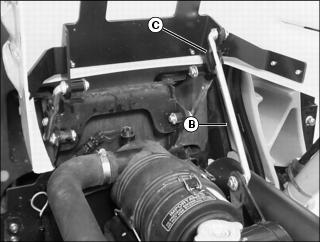
4. Raise hood until hood support rod (B) completely engages retaining clip (C).
Lowering
1. Pull hood downward to release hood support rod from retaining clip.
3. Push down on front of hood to lock the latch.
Removing and Installing Engine Side Panels
Removing Right Side Panel
1. Raise front loader boom and install loader boom service lock. (See Using Loader Boom Service Lock in the SAFETY section.)
2. Park the machine safely for service. (See Parking Safely in the SAFETY section.)
4. Grasp top of side panel. Pull outward to unsnap front and rear lock pins (A) from panel retainers (B).
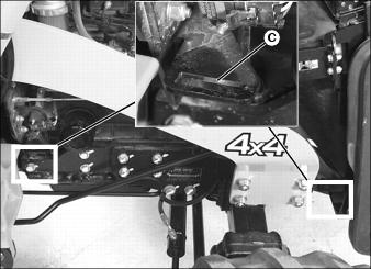
5. Lift bottom of side panel up and out of front and rear mounting bracket slots (C).
Installing Right Side Panel
1. Install side panel tabs into mounting bracket slots (C).
2. Align front and rear lock pins (A) with panel retainers (B) and snap into position.
Removing Left Side Panel
1. Raise front loader boom and install loader boom service lock. (See Using Loader Boom Service Lock in the SAFETY section.)
2. Park the machine safely for service. (See Parking Safely in the SAFETY section.)
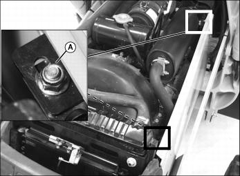
4. Remove two nuts (A) securing top of side panel.
5. Lift bottom of side panel up and out of front and rear mounting bracket slots (B).
Installing Left Side Panel
1. Install side panel tabs into mounting bracket slots (B).
2. Fasten top of side panel with nuts (A).
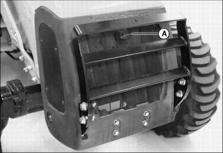
Checking Backhoe Boom-to-Dipperstick Pivot Pin Bolt Torque
1. Check torque on the boom-to-dipperstick pivot pin bolt (A).
· Tighten bolt to 620 N·m (460 lb-ft).
Replacing Backhoe Bucket Teeth

1. Carefully drive a chisel into location (A) between tooth (B) and adapter (C).