
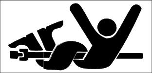
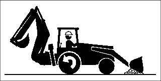
Operating Machine
Daily Operating Checklist
o Test safety systems. Perform safety interlock system checkout procedure.
o Check transmission oil level.
o Check fuel filter sediment bowl.
o Check air filter rubber dust unloading valve.
o Check radiator coolant level.
o Check and clean grille and side screens.
o Check area below machine for leaks.
o Lubricate loader pivot points.
o Lubricate backhoe pivot points.
o Lubricate optional multi-purpose bucket grease fittings.
Avoid Damage to Plastic and Painted Surfaces
· Do not wipe plastic parts unless rinsed first.
· Insect repellent spray may damage plastic and painted surfaces. Do not spray insect repellent near machine.
· Be careful not to spill fuel on machine. Fuel may damage surface. Wipe up spilled fuel immediately.
Operator Station
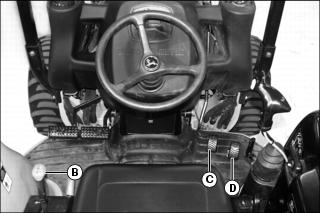
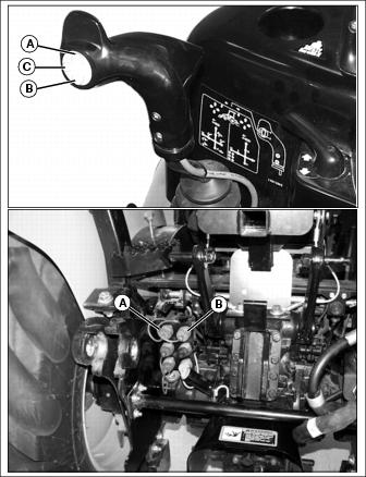
Right Side Controls
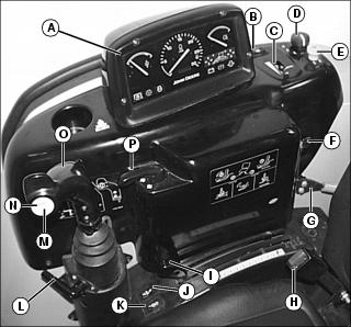
B - Repositioning Creeper Drive Direction Switch
C - Repositioning Creeper Drive Speed Control
G - Engine Speed Hand Throttle Lever
J - Third Selective Control Valve (SCV) Continuous Switch (optional)
K - Third Selective Control Valve (SCV) ON/OFF Switch (optional)
L - Selective Control Valve (SCV) Lock Lever
M - Third Selective Control Valve (SCV) Momentary Switch (optional)
N - Diverter Control Valve Diverter Switch (optional)
O - Dual Selective Control Valve (SCV) Handle
Left Side Controls
B - Transmission Range Shift Lever
Foot Controls
Floor Panel Controls
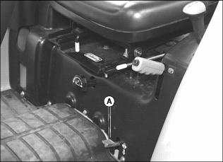
A - Seat Position Lock Release Lever
B - Operator Seat Adjustment Lever
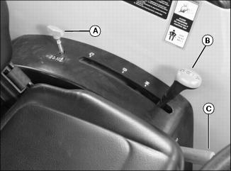
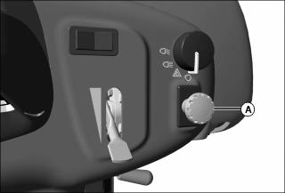
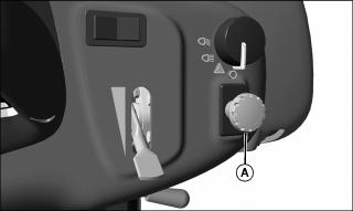
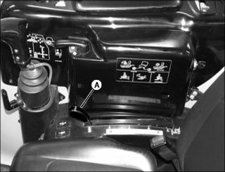
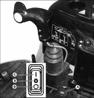
D - Rockshaft Rate-of-Drop Control Knob
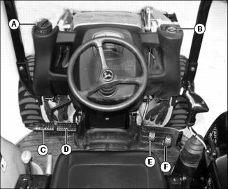
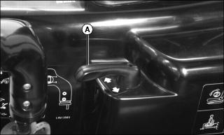
Using Steps and Handholds
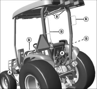
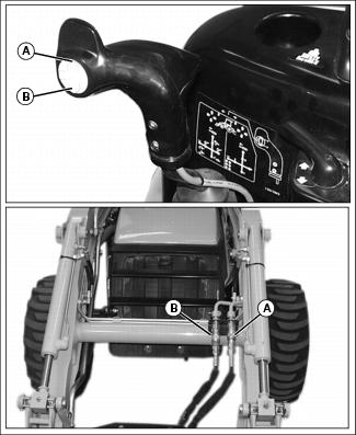
· Use steps (A) and handholds (B) when entering and exiting the operator station.
Do not enter or exit the backhoe on the right side of machine. |
· Use step (A) and handhold (B) when entering and exiting the backhoe.
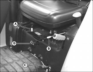
Using Operator Seat
Adjust Seat Position
Before starting engine to operate machine, adjust operator seat position.
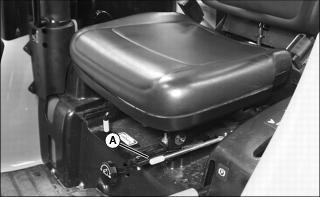
3. Slide seat forward or rearward to desired position.
4. Release lever to lock seat in position. Make sure all controls can be easily accessed.
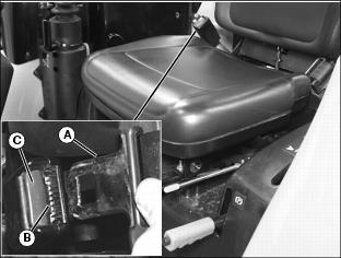
Operator Seat Facing Rear
Before operating backhoe, pivot and lock operator seat into position facing to the rear.
NOTE: Seat must be slid fully rearward before adjusting seat for backhoe operation.
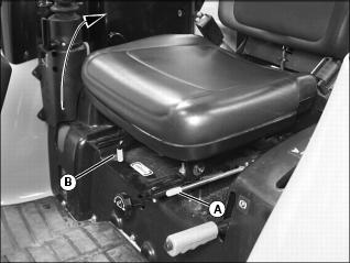
3. Slide seat fully rearward. Release lever to lock seat in position.
4. Pull lever (B) forward to release seat lock.
5. Rotate seat clockwise until fully lowered onto seat platform facing to the rear. Make sure safety lock (C) is fully engaged.
Operator Seat Facing Front

2. Pull lever (B) forward to disengage seat lock.
3. Rotate seat counterclockwise until fully lowered onto the seat platform facing to the front. Make sure safety lock is fully engaged.
Using Seat Belt
Fasten Belt
1. Pull belt end across operator lap.
2. Install tab (A) into buckle (B).
· A click will be heard when the tab locks into the buckle.
Release Belt
1. Press red button (C) to release seat belt allowing the belt to automatically retract.
Using Key Switch
NOTE: For cold weather starting, the intake air heater system can be activated by moving the key to the run position and pushing in the key.
Using Light Switch
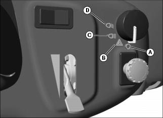
B - Warning flasher lights on.
C - Road Position: front work lights, taillights, and warning flasher lights on.
D - Field Position: front work lights, taillights, and optional rear work lights on.
Using Turn Signal Lever
· Move turn signal lever (A) left to signal a left turn.
· Move turn signal lever (A) right to signal a right turn.
Using the Instrument Panel
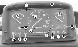
· Rated Engine Speed: 2600 rpm
Testing Safety Systems
Use the following checkout procedure to check for normal operation of machine.
If there is a malfunction during one of these procedures, Do not operate machine. See your John Deere dealer for service.
Perform these tests in a clear open area. Keep bystanders away.
Testing Rear PTO Switch
3. Pull the rear PTO knob to the engaged/on position.
4. Turn key switch to start position.
5. Push the rear PTO knob to the disengaged/off position.
6. Turn key switch to off position.
Testing Rear PTO/Seat Switch Interface
3. Push the rear PTO knob to the disengaged/off position.
4. Move the transmission range shift levers into the N (neutral) position.
6. Pull the rear PTO knob to the engaged/on position.
7. Raise up from operator's seat. Do not dismount machine.
8. Engine should stop. Engine shut-off solenoid must de-energize in 1/2 second, causing the engine to stop.
9. Push the rear PTO knob to the disengaged/off position.
10. Turn key switch to off position.
Using Fuel Shut-Off Valve
2. Remove side panel from right side of engine.
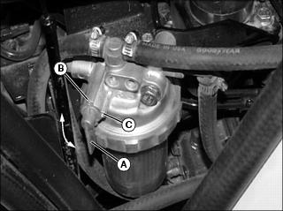
3. Open or close fuel shut-off valve lever (A) as required:
Using Brake Pedals
Using Brake Pedals As Driving Brake
1. Rotate brake pedal latch (A) counterclockwise until it locks into left turn brake pedal (B).
2. Depress either brake pedal to slow or stop the machine.
· With latch down, brakes should stop machine in a straight line.
Using Brake Pedals to Assist In Turning
IMPORTANT: Avoid damage! Do not apply turn brakes while an implement is engaged with the ground. Damage to the 3-point hitch and implement may occur. |
NOTE: Turn brake pedals can be used to make tighter turns and may reduce unnecessary backing.
1. Rotate brake pedal latch (A) clockwise until it stops against right turn brake pedal (C). The brake pedals will now function independently.
· To make a tighter left turn, depress left turn brake pedal (B) while turning to the left.
· To make a tighter right turn, depress right turn brake pedal (C) while turning to the right.
Using Park Brake
Locking Park Brake
1. Lock both brake pedals together using brake pedal latch.
2. Press down completely on brake pedals with foot to hold the machine in position.
3. Pull park brake lever (A) up to the locked position.
Unlocking Park Brake
1. Press down completely on brake pedals with foot to hold the machine in position.
2. Lift the park brake lever (A) slightly while pressing in on the lock release button (B).
3. Fully lower park brake lever down to the unlocked position and release the lock button.
4. Remove foot from brake pedals when ready to move machine.
Using Throttle Controls
Use the hand throttle lever to set engine speed.
· Rated Engine Speed - 2600 rpm
Starting the Engine
NOTE: It is recommended to install optional engine block heater and hydraulic oil heater if operating machine in temperatures below -18°C (0°F).
If temperature is below 5°C (40°F), follow the cold weather starting steps in this section.
1. Open the fuel shut-off valve.
3. Push the rear PTO (A) knob to the disengaged/off position.
4. move transmission range shift lever (b) to neutral position.
5. Remove foot from forward (C) and reverse (D) travel pedals.
6. Set hand throttle lever to the 1/3 fast position.
7. Turn ignition key switch to the run position.
8. Check instrument panel indicator lights:
· Alternator/battery charging light will glow.
· Park brake light will illuminate if park brake is locked.
· Engine oil pressure light will glow.
· Diagnostic indicator light will flash one time.
9. For cold weather starting, use the intake air heater system. Activate the intake air heater system by pushing in the ignition key switch with the key, and holding it there for the required time:
· 10 - 15 seconds for temperatures as low as -18°C (0°F).
· 15 - 30 seconds for temperatures below -18°C (0°F).
10. Turn key switch to the start position. Release key when engine starts.
11. Check instrument panel indicator lights:
· Diagnostic indicator light will flash one time.
· Engine oil pressure light should go out within 5 seconds.
NOTE: Set engine speed to 1500 rpm if indicator light does not go out after 10 seconds.
· Alternator/battery charging light should go out within 10 seconds.
· If indicator lights stay on longer than the given time intervals, stop the engine and check for cause.
IMPORTANT: Avoid damage! In cold weather, run engine several minutes to allow engine oil and transmission oil to warm. |
NOTE: It is normal for the engine to be louder and for blue-white exhaust smoke to be present during engine warm-up. The amount of exhaust smoke depends on air temperature.
· In warm weather, set hand throttle lever to 1500 rpm for 1 minute without load.
· In cold weather, set hand throttle lever to 1500 rpm for 5 minutes without load.
Idling the Engine
NOTE: Allowing engine to idle for long periods of time will waste fuel and cause carbon build-up.
1. Adjust hand throttle lever to set engine speed at 1050 rpm (slow idle speed).
Starting a Stalled Engine
IMPORTANT: Avoid damage! If engine stalls while operating under load, start engine immediately to prevent abnormal heat build-up in engine. |
1. Push the rear PTO knob to the disengaged/off position.
2. Move range transmission to neutral position.
3. Remove foot from forward travel and reverse travel pedals.
4. Start engine. Continue with normal operation, or set engine at 1050 rpm (slow idle speed) for 2 minutes before stopping the engine.
Stopping the Machine
Normal Stopping
1. Position the machine on a firm, level surface.
2. Stop machine motion by removing foot smoothly from forward or reverse travel pedals.
3. Move range transmission to position other than neutral.
4. Push the rear PTO knob to the disengaged/off position.
5. Lower any front implement to the ground.
6. If backhoe is installed, raise and center the backhoe.
9. If attached, lower any rear implement to the ground.
IMPORTANT: Avoid damage! Do not stop engine immediately after hard or extended operation. Keep engine running at 1050 rpm for about 2 minutes to prevent heat build-up. |
10. Adjust hand throttle lever down to set engine speed at 1050 rpm (slow idle speed). Allow engine to idle for 2 minutes.
12. Turn ignition key switch to the off position.
14. Wait for the engine and all moving parts to stop before leaving the operator's station.
Emergency Stopping
1. Remove foot from forward or reverse travel pedals.
3. Turn key switch to off position. Do not release brake pedals until all moving parts have stopped.
Operating the Transmission

The transmission range shift lever (A) provides three speed ranges.
The transmission range shift lever is used in conjunction with the forward travel pedal (B) and reverse travel pedal (C).
1. Choose a speed range to match work application.
NOTE: It may be necessary to move the machine forward and backward slightly to unload the gears for easier shifting.
· A - Low speed/high power operations such as grading, loading, or positioning backhoe.
· B - Operations including moderate grading, loading, and hauling.
· C - High speed operations such as transport.
Driving Machine
IMPORTANT: Avoid damage! To prevent transmission damage, stop machine motion completely before shifting the range shift lever. |
3. Choose A, B, or C speed range on range shift lever to match work application.
4. Move hand throttle lever to desired operating speed.
NOTE: The machine will not move if operator is not in seat when attempting to drive machine. The machine will stop if operator rises out of seat while the machine is in motion.
5. Slowly depress forward travel pedal downward to travel forward. Slowly depress reverse travel pedal downward to travel in reverse.
· The farther either travel pedal is depressed, the faster the machine will travel.
6. Release travel pedal to stop machine and change speed range.
7. Fully stop machine motion before turning off ignition.
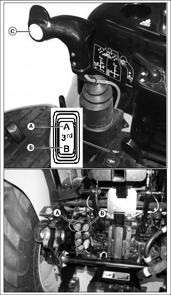
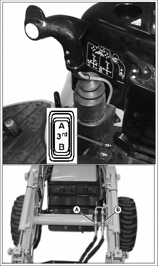
Using Repositioning Creeper Drive Control
NOTE: The repositioning creeper drive control is operational in both forward and reverse.
3. If lowered, raise the front end loader and the backhoe stabilizers to clear surface.
4. Choose A or B speed range on transmission range shift lever to match work application.
5. Move hand throttle lever to desired operating speed.
NOTE: The machine will not move if operator is not in seat when attempting to drive machine. The machine will stop if operator rises out of seat while the machine is in motion.
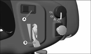
6. Depress and hold directional switch (A) in desired travel direction.
NOTE: Motion alarm will sound as soon as direction control switch is moved.
7. Move and hold speed control lever (B) to desired speed position.
· The farther the speed control lever is moved, the faster the machine will travel.
8. Release directional switch or speed control lever to stop motion.
9. Fully stop machine motion before turning off ignition.
Using Differential Lock
To prevent tipping, do not engage differential lock under any of the following conditions: |
The differential lock is used to provide better traction when the rear wheels start to slip. Engaging the differential lock will lock the right and left side rear axles together and cause both rear wheels to turn at equal speeds for maximum traction.
NOTE: Turning radius is increased when the differential lock is engaged. To assist turning, release the differential lock and use the turn brake pedals.
Engaging Differential Lock
1. Stop or slow machine movement.
NOTE: Differential lock will remain engaged as long as rear wheel slippage occurs. If tires slip and regain traction repeatedly, hold down pedal with foot so differential lock remains engaged.
2. Push down on differential lock pedal (A) to engage differential lock.
Disengaging Differential Lock
NOTE: Rear wheel slippage will keep differential lock engaged. Lock will automatically disengage when traction equalizes.
1. Remove foot from differential lock pedal.
2. If lock does not disengage when foot is removed from pedal, depress one turn brake pedal and then the other.
Using Mechanical Front Wheel Drive (MFWD)
Mechanical front wheel drive (MFWD) enables the powertrain to drive all four wheels for improved traction on difficult ground conditions and provides 4-wheel braking. MFWD can be engaged and disengaged on-the-go with light loads and on low traction surfaces.
IMPORTANT: Avoid damage! Always disengage MFWD when driving on a paved surface. Do not install tire chains on machine front wheels. Chains will strike and damage machine. |
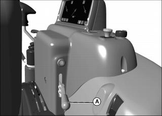
1. Pull up on knob (A) to engage MFWD.
NOTE: It may be necessary to reduce engine load to disengage front wheel drive.
2. Push down on knob (A) to disengage MFWD.
Tips for Operating MFWD
· Maintain front tire pressure at maximum allowable level to ensure proper tire performance in all field conditions.
· Engage MFWD to provide four-wheel braking.
· Disengage MFWD when driving machine to or from work site to increase front tire life.
Using the Power-Take-Off (PTO) Safely
Using Rear PTO (Operator On Seat)
Engaging Rear PTO
2. Stop machine motion by removing foot from forward and reverse travel pedals.
NOTE: The starter will not crank if the rear PTO knob is pulled to the engaged/on position. If the operator leaves the seat with the engine running and the rear PTO engaged, the safety interlock system will stop the engine and all implements.
3. Reduce throttle setting to below 1500 rpm.

4. Pull the rear PTO knob (A) to the engaged/on position to engage the rear PTO.
· The instrument panel PTO engaged light will illuminate when the rear PTO is engaged.
5. Adjust the hand throttle lever upward to the desired speed for implement used.
NOTE: The tachometer indicates a standard 540 PTO at engine speed of 2600 rpm.
Disengaging Rear PTO
1. Set engine speed to 1050 rpm (slow idle speed).
2. Push the rear PTO knob (A) to the disengaged/off position to disengage the rear PTO.
· The instrument panel PTO engaged light will go out when the rear PTO is disengaged.
Using Rear PTO (Operator Off Seat)
NOTE: The rear PTO can be engaged with the operator off the seat.
Engaging Rear PTO
2. Move transmission range shift lever to the N (neutral) position.
4. Push the rear PTO knob (A) to the disengaged/off position.
NOTE: The starter will not crank if the rear PTO knob is pulled to the engaged/on position.
5. Start the engine and adjust throttle setting to 1500 rpm.
6. Get off the operator's seat.
7. Pull the rear PTO knob (A) to the engaged/on position to engage the rear PTO.
· The engine should continue to run.
· The instrument panel PTO engaged light will illuminate when the rear PTO is engaged.
8. Adjust the hand throttle lever upward to the desired speed for implement used.
NOTE: The tachometer indicates a standard 540 PTO at engine speed of 2600 rpm.
Disengaging Rear PTO
1. Set engine speed to 1050 rpm (slow idle speed).
2. Push the rear PTO knob (A) to the disengaged/off position to disengage the rear PTO.
· The instrument panel PTO engaged light will go out when the rear PTO is disengaged.
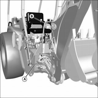
Using Drawbar Hitch (Optional)
IMPORTANT: Avoid damage! Maximum static vertical load on drawbar should not exceed the maximum recommendations. Drive slowly with heavy loads. |
Maximum Drawbar Loads
Certain heavy equipment such as a loaded single-axle trailer can place excessive strain on the drawbar. Strain is greatly increased by speed and rough ground. Do not exceed the following maximum static vertical loads on drawbar:
Maximum static vertical load 255kg (562 lb)
Removing Drawbar
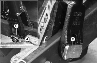
1. Remove spring locking pin (A) and drilled pin (B).
2. Pull drawbar from tractor bracket.
Installing Drawbar
1. Install drawbar into tractor mounting bracket.
2. Align hole for installation of drilled pin (B).
3. Install drilled pin (B) up from bottom of machine. Secure with spring locking pin (A).
Using 3-Point Hitch
NOTE: The 3-point hitch on your machine is classified as a Category 1 hitch.
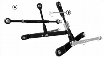
· Place center link (A) in storage hook (B) when the hitch is not in use.
Positioning Center Link
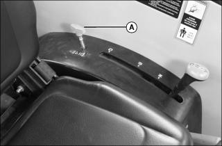
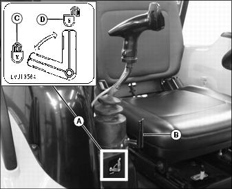
Using Rockshaft Control Lever
Use rockshaft control lever (A) to raise and lower equipment attached to the 3-point hitch.
The calibrated settings are for reference only and do not signify specific operating depths. When the rockshaft control lever is moved forward, the draft links will lower closer to the ground.
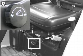
Using Rate of Drop/Lock Valve
IMPORTANT: Avoid damage! To prevent overheating hydraulic oil and damaging machine, do not raise rockshaft when drop/lock valve is closed. |
The rate of drop/lock valve controls the rate of rockshaft drop when the rockshaft control lever is operated. This provides direct rate of drop control for 3-point hitch mounted implements. The valve can also be used to hydraulically lock the rockshaft (three-point hitch) in a desired position.
Using Draft Links
1. Slowly back machine into position to align draft links with implement lift brackets.
2. Park machine safely. (See Parking Safely in the SAFETY section.)
3. Connect draft links to the implement.
Leveling Implement Front-to-Rear
Leveling a 3-point hitch mounted implement front-to-rear is accomplished by adjusting the length of the center link:
1. Park machine safely. (See Parking Safely in the SAFETY section.)
3. Rotate handle (B) to lengthen or shorten the center link.
Leveling Implement Side-to-Side - Manual
Use turn handle (A) on the right adjustable lift link (B) to level a 3-point hitch implement side-to-side.
1. Park machine safely. (See Parking Safely in the SAFETY section.)
2. Raise lift link turn handle (A) from transport position and locking tab (C).
3. Rotate handle approximately 1/2 turn. Lower handle notch onto roll pin (D).
4. Rotate handle (A) to raise or lower draft link until 3-point hitch mounted implement is level from side-to-side.
5. Return handle to the transport position with handle notch on locking tab.
Leveling Implement Side-to-Side - Hydraulic
Use the loader SCV control to adjustable lift link to level a 3-point hitch implement side-to-side.
3. Retract or extend lift link cylinder to raise or lower draft link until 3-point hitch mounted implement is level from side-to-side.
Adjusting Implement Side-to-Side Sway
NOTE: Check implement operator's manual procedure for adjusting anti-sway links. When anti-sway links have been properly adjusted, side sway of implement is controlled by position of links.
IMPORTANT: Avoid damage! The anti-sway links must be adjusted to hold the implement in place as close to the centerline as possible. Do not use the anti-sway links in the float position. |

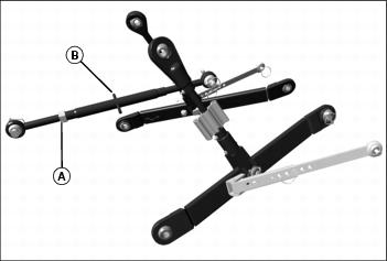
Use left and right anti-sway links (A) to adjust 3-point hitch implement side-to-side sway.
1. Park machine safely. (See Parking Safely in the SAFETY section.)
2. Remove locking ring (B) and drilled pin (C).
3. Slide links to adjust length.
4. Install drilled pin and locking ring (B).
5. From operators seat, start engine.
6. Slowly move draft links through full range of motion to check for clearance.
8. Repeat adjustment procedure if needed.
Adjusting Draft Links to Float Position
Adjusting 3-point hitch stops to the float position will allow both draft links to raise slightly as the implement follows ground contour.
Adjust stops to the float position for 3-point hitch implements such as a cultivator or mower. These implements will have ground gauging skids or wheels which may otherwise cause the implement to twist relative to the machine.
1. Park machine safely. (See Parking Safely in the SAFETY section.)
2. Remove quick-lock pin (A) and bushing (B).
3. Remove float pin (C) slightly and rotate into vertical position.
4. Install bushing (B) onto float pin in vertical position.
5. Install quick-lock pin (A).
Adjusting Draft Links to Rigid Position
Adjusting 3-point hitch stops to the rigid position will restrict movement of the draft links as the implement follows ground contour.
Adjust stops to the rigid position for 3-point hitch implements such as plows and ground engaging implements that should not twist relative to the machine.
1. Park machine safely. (See Parking Safely in the SAFETY section.)
2. Remove quick-lock pin (A) and bushing (B).
3. Remove float pin (C) slightly and rotate into horizontal position.
4. Install bushing (B) onto float pin in horizontal position.
5. Install quick-lock pin (A).
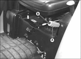
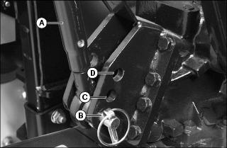
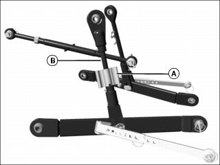
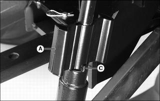
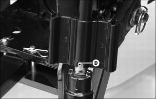
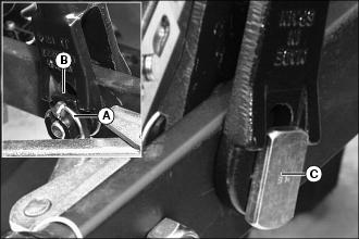
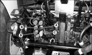
Using Loader Selective Control Valve (SCV) Lock Lever
The selective control valve (SCV) lock lever allows the operator to lock the dual SCV handle and minimize rapid movement of loader and attachments.
· Operation of the lock lever is indicated on label (A).
· Move lock lever (B) to horizontal position (C) to prevent dual SCV handle movement in all directions.
· Move lock lever (B) to the vertical position (D) to allow dual SCV handle movement in all directions.
Using Standard Hydraulic Dual Selective Control Valve (SCV)
The dual SCV will control the lifting and lowering of the boom as well as the tilting and roll-back of the bucket.
The handle has positions to allow the boom to float with the contour of the ground, and allow the bucket to be tilted forward using return oil to increase tilting speed.
Additional functions are available with optional SCV packages.
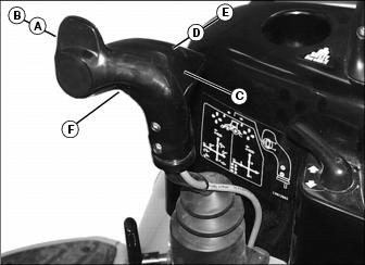
Refer to information label to the right of dual SCV handle if further operating assistance is required.
Using Optional Hydraulic Third Selective Control Valve (SCV)
This machine can be equipped with an optional hydraulic third Selective Control Valve (SCV) and hydraulic outlets to operate front mounted hydraulically-driven implements.
Standard hydraulic dual selective control valve (SCV) operation is unchanged.
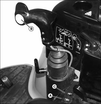
Using Optional Third SCV On/Off Switch
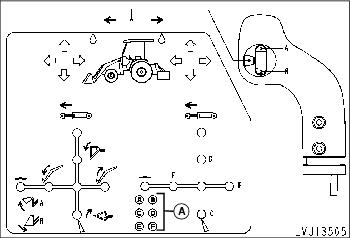
Third SCV uses a three position On/Off switch (A) to enable use of third SCV. A light on instrument panel will illuminate to show that third SCV is on.
Using Optional Third SCV Momentary Switch
The third SCV may be operated in a momentary condition to operate attachments such as extending or retracting a cylinder or short use of a hydraulic motor. This is a direct acting on/off circuit. The attachment will receive full hydraulic flow in direct response to the use of the switch.
1. Turn on third SCV switch to enable momentary switch.
2. Depressing the top (A position) of momentary switch will allow flow from third SCV circuit out female quick coupler (A) and returning on male quick coupler (B) as long as the switch is depressed.
3. Depressing the bottom (B position) of momentary switch will allow flow from third SCV circuit out male quick coupler (B) and returning on female quick coupler (A) as long as the switch is depressed.
Refer to information label to the right of dual SCV handle if further operating assistance is required.
Using Optional Third SCV Continuous On Switch
The third SCV may be operated in a continuous condition to operate attachments such as hydraulic motors. This is a direct acting on/off circuit. The attachment will receive full hydraulic flow in direct response to the use of the switch.
1. Turn on third SCV switch to enable the continuous switch.

2. Moving the continuous switch to the A position will provide continuous flow from third SCV circuit out female quick coupler (A) and returning on male quick coupler (B).
3. Moving the continuous switch to the B position will provide continuous flow from third SCV circuit out male quick coupler (B) and returning on female quick coupler (A).
Refer to information label to the right of dual SCV handle if further operating assistance is required.
Using Optional Diverter Switch
1. Turn on third SCV switch to enable diverter switch.
2. Front indicator light will be illuminated when third SCV is enabled for front hydraulic controls. Normal operation will enable front hydraulic controls.
3. Rear indicator light will be illuminated when diverter is enabled for rear hydraulic controls. The operator must select rear control operation.
4. Press diverter switch (A) to select rear hydraulic control. Press diverter switch again to select front hydraulic control.
Using Optional Hydraulic Third Selective Control Valve (SCV) with Diverter
This machine can be equipped with an optional hydraulic diverter control valve and rear hydraulic outlets with the third selective control valve (SCV) to operate rear mounted as well as front mounted hydraulically-driven implements.
Standard hydraulic dual selective control valve (SCV) operation is unchanged. Normal operation will be for forward controls. To operate rear mounted attachments the third SCV must be turned on and diverter switch engaged.
Using the E and F quick couplers will provide hydraulic flow proportional to dual SCV handle movement out either quick coupler. In the neutral position, hydraulic fluid will be locked into the attachment. In the float position, hydraulic pressure is relieved from both quick couplers and items such as hydraulic motors will be unlocked.
Using the C and D quick couplers will provide hydraulic flow proportional to dual SCV handle movement out either quick coupler. In the neutral position, hydraulic fluid will be locked into the attachment. In the regen position, hydraulic pressure is supplied to both quick couplers and items such as hydraulic cylinders will extend.
Using the A and B quick couplers will provide full flow operation either momentarily or continuously out of either quick coupler. The attachment will receive full hydraulic flow in direct response to the use of the switch. In the off position, hydraulic fluid will be locked into the attachment.
Using Optional Third SCV Momentary Switch with Diverter
The third SCV may be operated in a momentary condition to operate attachments such as extending or retracting a cylinder or short use of a hydraulic motor. This is a direct acting on/off circuit. The attachment will receive full hydraulic flow in direct response to the use of the switch.
1. Turn on third SCV switch to enable momentary switch.
Picture Note: Rear quick couplers only available with diverter option.
2. Press diverter switch (C) to select rear hydraulic control.
3. Depressing the top (A) of momentary switch will allow flow from third SCV circuit out quick coupler (A) and returning on quick coupler (B) as long as the switch is depressed.
4. Depressing the bottom (B) of momentary switch will allow flow from third SCV circuit out quick coupler (B) and returning on quick coupler (A) as long as the switch is depressed.
Refer to information label to the right of dual SCV handle if further operating assistance is required.
Using Optional Third SCV Continuous On Switch with Diverter
The third SCV may be operated in a continuous condition to operate attachments such as a hydraulic motors. This is a direct acting on/off circuit. The attachment will receive full hydraulic flow in direct response to the use of the switch.
1. Turn on third SCV switch to enable continuous switch.
Picture Note: Rear quick couplers only available with diverter option.
2. Press diverter switch (C) to select rear hydraulic control.
3. Move continuous switch to A position will allow continuous flow from third SCV circuit out quick coupler (A) and returning on quick coupler (B).
4. Move continuous switch to B position will allow continuous flow from third SCV circuit out quick coupler (B) and returning on quick coupler (A).
Refer to information label to the right of dual SCV handle if further operating assistance is required.
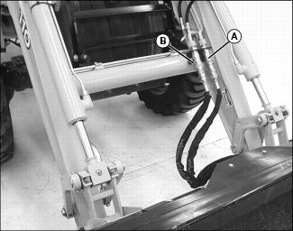
Connecting Implement Hydraulic Hoses
Relieving Hydraulic Hose Pressure
1. Park machine safely. (See Parking Safely in the SAFETY section.)
2. Leave engine off and move key switch to RUN position.
3. Turn the third SCV switch on.
4. Switch the third SCV continuous flow switch to the A position and connect the implement to the RH coupler (A).
5. Switch the third SCV continuous flow switch to the B position and connect the implement to the LH coupler (B).
6. Turn key switch to OFF position.
Connecting Hydraulic Hoses
1. Relieve hydraulic hose pressure before connecting hydraulic hoses.
2. Pull back on outer knurled ring (A) and push couplers together with a firm continuous motion until couplers lock into place.
Removing Hydraulic Hoses
1. Relieve hydraulic hose pressure before removing hydraulic hoses.
2. Push hydraulic hose in while pulling back on outer knurled ring (F). The coupler will unlock and hydraulic hose can be removed.
Using QUIK-TATCH® Attachment Mounting System
Installing an Attachment
1. Align machine with attachment.
2. Tilt mounting plates (A) slightly forward.
3. Drive forward, raise boom, and guide top of the mounting plates under attachment mounting brackets (B).
4. Raise and roll-back mounting plates. The back of attachment should rest against the front of mounting plate.
5. When attachment is fully supported, lower the boom and tilt attachment forward, stopping with the bottom edge of attachment level, about 50 mm (2 in.) above ground.
6. Lock park brake, and exit machine.
7. Push the two latch handles (C) down to lock attachment to the QUIK-TATCH.
8. Raise boom and tilt attachment forward at a slight downward angle so that bottom of the QUIK-TATCH is visible.
9. Visually inspect attachment mechanism to verify that pins are fully engaged in slots on the back of attachment.
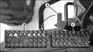
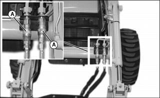
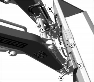
10. Connect attachment hydraulic hoses, if equipped, to quick couplers (A and B).
Removing an Attachment
1. Position machine and attachment on firm level ground.
2. Disconnect hydraulic hoses from attachment if so equipped.
3. Pull latching handles up to the unlatched position to release pins from lower attachment tabs. Be sure latch handles are fully raised.
4. Lower attachment so that it rests securely on ground.
5. Tilt mounting plate forward and back machine away from attachment at the same time.
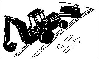
Worksite Layout
For an efficient operation, arrange the job to minimize the time required to perform the work cycle.
Before the work cycle begins, walk the worksite to uncover any hazards, and clear worksite of unauthorized personnel. Take a few minutes to level off the work area if not smooth.
When selecting the dump site, consider wind direction and ground slope. Whenever possible, position the dump site so that the wind will carry dust away from the operator.
Minimize transport distances for a fast work cycle.
Operating Tips
Do not knock down stakes or grade markers which aid in identifying surface and slope changes.
Use proper equipment to best suit terrain and debris being worked with.
Loose, fragmented material will dump quickly from the bucket. To break up material as it enters bucket and avoid sticking, excavate in thin layers.
If cleaning bucket by hitting against stops, use minimum amount of force to avoid cylinder damage. If rapping bucket lightly does not work, clean bucket by hand. Do not attempt to clean bucket by striking against the ground or another object.
Transporting Loaded Bucket
|
Do not push against objects with the boom fully raised or damage to the boom or boom cylinders may occur. Do not push forward with the bucket fully dumped or damage to the bucket cylinders may occur. |
Never transport a loaded bucket at full height. Keep the bucket as low to the ground as possible for better stability and visibility.
Reducing speed when driving over rough terrain, carrying a heavy load, or working in a congested area will increase your ability to control the machine. Avoid rough terrain, rocks, curbs, and ditches whenever possible.
When backing out and transporting a load, raise the bucket just high enough to clear obstacles in your path. Raising a loaded bucket too high reduces stability.
When backhoe (if installed) is not being used, backhoe boom must be locked in fully raised and centered position. Curl bucket and retract dipperstick.
Proper Work Angles
Work perpendicular to stockpile to prevent highest part of pile from collapsing onto machine.
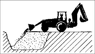
Work perpendicular to excavation to prevent cave-ins. Do not operate near the edge of an excavation or trench.
Operating on a Slope
Drive straight up or down slopes with loader near the ground, and backhoe (if installed) in locked, centered, and dipperstick retracted position with bucket curled.
Keep bucket high enough above the ground and curled back slightly to prevent digging into the ground.
Reduce drive speed to prevent bouncing.
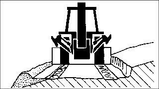
Filling the Bucket
There are two basic methods of filling a bucket from a pile - Arc Penetration and Step Penetration. Judge the type of penetration needed for loading and vary the methods to suit the materials.
Arc Penetration
Arc penetration is best suited for loose or light materials.
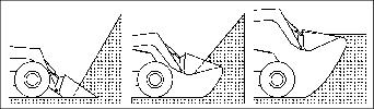
With the arc penetration method, the bucket is forced into the pile and rolled back, then raised in a continuous upward arc until the bucket is filled. When activating both the lift and bucket hydraulic circuits at the same time, the lift or roll-back system may occasionally stall the loader. When this happens, disengage either the lift or roll-back function to allow maximum hydraulic force to one set of the cylinders. If stalling happens frequently, use the step penetration method.
Step Penetration
With the step penetration method, the bucket is forced into the pile at ground level with the bucket bottom horizontal to the ground. Force the bucket into the pile as far as possible during the initial thrust. Raise the bucket about a foot and then force it further into the pile. Repeat this cycle as many times as necessary to fill the bucket.
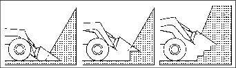
Digging
When digging, remove a thin layer with each pass. This method is efficient and minimizes wheel slippage. When encountering firmly packed materials, quickly move the dual SCV handle side to side (bucket tilt and roll back) to assist penetration. Teeth can be installed on the bucket to provide better penetration.
Returning Bucket to Loading Position
Immediately after the bucket has been fully dumped, begin the roll-back cycle as the machine is backed away from the dump site. Repositioning the bucket for the filling cycle while the boom is lowering is a good time saver. Fine adjustments in bucket position can be made as the machine begins forward on the filling cycle, thereby saving a period of dead time between the dumping and filling cycles.
Bulldozing with Bucket
|
Do not push against objects with the boom fully raised or damage to the boom or boom cylinders may occur. Do not push forward with the bucket fully dumped or damage to the bucket cylinders may occur. |
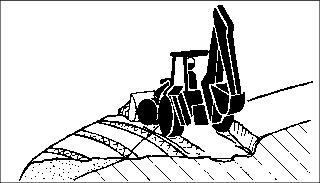
The machine can be used for bulldozing by controlling the tilt of the bucket. With the bucket close to the ground, remove as little material as possible from top surface. Let material spill from bucket to fill in low spots.
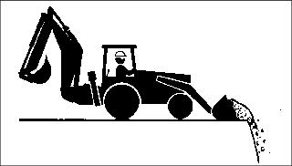
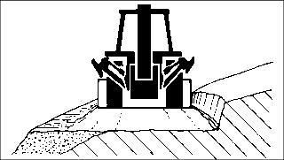
Backdragging with Bucket
The machine can be used for leveling by placing the bucket in the dump position and back dragging loose soil. The tilt of the bucket will control the amount of soil that is transported.
Place the boom control valve spool in the detent (float) position to allow the bucket to follow the ground contour and deposit soil in the low areas.
Backfilling
Backfilling an Excavation
As an excavation is filled nearly to grade, begin to compact material by slowly moving front wheels onto fill material while gradually emptying loader bucket. Front wheels will compact loose material which will support machine as it moves further onto filled area.
Backfilling Next to a Building
When backfilling next to a building, push load as close as possible with loader bucket, then backdrag to pull excess material away.
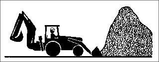
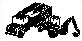
Truck Loading
Level and smooth loading area before loading trucks to increase machine stability.
When backhoe (if installed) is not being used, backhoe boom must be locked in fully raised and centered position. Curl bucket and retract dipperstick.
Ensure working area is clear of all persons, including truck driver, before loading truck.
Park truck close to stockpile to reduce travel time.
If possible, load truck on driver's side for easy communication with driver.
Whenever possible, position truck so that the wind will carry dust away from the operator.
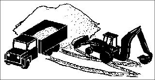
Follow an angled path between truck and stockpile.
Raise loader while moving toward truck and lower while moving away from truck to reduce load time.
Load truck from center front to center rear. Do not position loader over truck cab.
Dump load into truck at a steady pace (rather than abruptly) to minimize stress on truck.
If loading large rock, first place a load of smaller rock onto truck to cushion impact of large rock.
Benching
Start benching on a level surface. If necessary, use backhoe bucket (if installed) to create a level starting point.
1. With bucket positioned at a slightly downward angle, lower bucket into ground and drive forward.
2. Create a windrow of spoil material to build the bench.
NOTE: Keep material in bucket while moving forward to fill low spots on bench.
3. Push windrow at a 45extend bench.
4. Compact windrow spoil with leading front tire only.
5. Make a final grading pass to straighten uphill bank and level bench.
Dislodging the Machine
In most cases, when a machine becomes bogged down, the bucket can be used to push the machine to more solid ground.
1. Raise the boom and tilt the bucket forward so that the cutting edge contacts the ground.
2. Lower the boom and curl the bucket (maintain contact with the ground) while pressing on the reverse drive pedal.
3. Repeat this cycle as many times as necessary to move the machine to solid ground.
Ballasting Machine
Ballasting this machine should not be done with backhoe installed. It is recommended that if ballast is needed, a ballast box totalling 567 kg (1250 lb), or a 567 kg (1250 lb) box scraper be mounted to the 3-point hitch.
Using Optional Rear Ballast Box
IMPORTANT: Avoid damage! Do not overload tires. Do not exceed tire maximum inflation pressure or maximum load capacity. |
The rear ballast box is used for carrying ballast on the 3-point hitch. The ballast box may be weighted up to 567 kg (1250 lb).
Tire Capacities
Verify maximum tire inflation pressure and maximum load information embossed into the tire side wall.
Using Liquid Weight in Tires
NOTE: Use of alcohol as ballast is not recommended. Calcium chloride solution is heavier and more economical.
A solution of water and calcium chloride provides safe economical ballast, and will prevent freezing. If used properly, it will not damage tires, tubes, or rims.
A mixture of 0.4 kg of calcium chloride per liter of water (3.5 lb/gal), will not freeze solid above -45° C (-50° F).
Fill tires at least to valve stem level (minimum 75% full). Less solution would expose part of rim, possibly causing corrosion.
Using Tire Sealant
Front Tires
IMPORTANT: Avoid damage! Damage to tires and drive train will occur if: |
1. Park machine safely. (See Parking Safely in the SAFETY section.)
2. Use TY16236 tire sealant for tires without calcium chloride to fill front tires.
3. Follow instructions with tire sealant to fill the front tires.
4. When complete the tires must not be harder than if inflated with air to 345 kPa (50 psi).
Rear Tires
1. Park machine safely. (See Parking Safely in the SAFETY section.)
2. Use either TY15833 tire sealant for tires without calcium chloride or TY6378 tire sealant for tires with calcium chloride to fill rear tires.
3. Follow instructions with tire sealant to fill the rear tires.
4. When complete the tires must not be harder than if inflated with air to 110 kPa (16 psi).
Transporting Machine on Trailer
NOTE: Check state and local regulations for tow vehicle and trailering requirements before transporting the Tractor Loader Backhoe. A trailer with a minimum 4536kg (10,000 lb) gross vehicle weight rating (GVWR) and an appropriate tow vehicle are required to transport the machine. Carrying additional equipment on the trailer will increase the GVWR requirement.
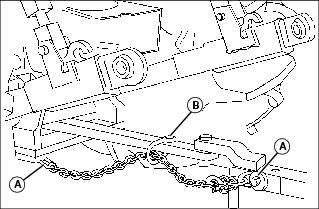
1. Drive machine forward onto trailer or truck.
· Engage boom and swing locks into transport position
· Lower backhoe bucket flat onto the deck and secure with chains to the deck.
IMPORTANT: Avoid damage! Do not fasten chains to, or put chains across the boom or bucket cylinders. Damage to cylinders may occur. |
8. Fasten machine to trailer with heavy-duty straps, chains, or cables. Both front and rear straps must be directed down and outward from machine. Trailer must have signs and lights as required by law.
9. Tie down loops are provided under front frame and backhoe.
Transporting Machine
Driving Machine Safely on Roads
Observe the following precautions when operating the machine on a road:
· Make sure brake pedals are locked together with the brake pedal latch.
· Make sure warning lights, and optional SMV (Slow Moving Vehicle) emblem, if equipped, are clean and visible. If towed or rear-mounted equipment obstructs these safety devices, install warning lights and SMV emblem on equipment.
· Rotate light switch to road position.
· Drive slowly enough to maintain safe control at all times. Slow down for hillsides, rough ground, and sharp turns, especially when transporting heavy, rear-mounted implements.
· Disengage the MFWD to reduce tire wear.
Pushing or Towing Machine
1. Push the rear PTO knob to the disengaged/off position.
2. Disengage the differential lock.
4. Move range transmission shift lever to N (neutral) position.
6. Make sure brake pedals are locked together with the brake pedal latch to slow or stop machine.
Towing Loads
1. Hitch the towed load only to the drawbar. Lock the drawbar and pin in place.
2. Install a safety chain to the machine drawbar support and to the towed load. Provide only enough slack to permit turning.
Towing Capacity
Using Safety Chain
1. Use the appropriate adapter parts (A) to attach the safety chain to the machine drawbar support and to the towed load. Provide only enough slack to permit turning.
2. Install additional attaching points (B) for the chain on drawbar to reduce slack in chain when necessary.
3. Remove the safety chain and store when not in use.
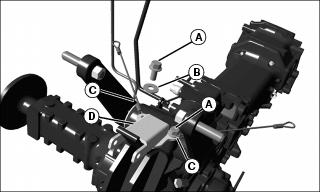
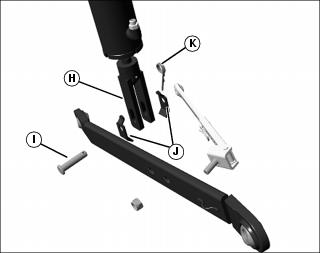
Installing and Removing 3-Point Hitch (Optional)
Installing Center Link
1. Park machine safely. (See Parking Safely in the SAFETY section.)
2. Install storage hook (A) into existing bracket (B).
3. Fasten storage hook to bracket with flat washer (C) and cotter pin (D).
4. Align center link (E) with mounting bracket holes (F).
· Choose top, middle or bottom set of holes based upon weight of intended load.
5. Install attaching pin (G) and quick-lock pin (H).
6. Install center link into storage hook.
Installing Lift Links
1. Install lift link (A) onto left rockshaft arm pin (B).
2. Install adjustable lift link (C) onto right rockshaft arm pin (D).
3. Fasten each lift link with a quick-lock pin.
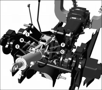
Installing Draft Links and Anti-Sway Links
Picture Note: Left side shown.
1. Install draft link (A) onto pin (B) on each side of transaxle.
2. Fasten each draft link with a quick-lock pin (C).
3. Locate anti-sway link (D) into mounting bracket (E) on each side of subframe.
4. Fasten anti-sway link to each bracket using drilled pins (F) and wire locking rings (G).
Picture Note: Left side shown.
5. Raise draft link and align lift link clevis (H) with draft link hole (I).
6. Install float pin (J) through clevis and draft link from inside to outside in vertical position.
7. Install bushing (K) onto float pin in vertical position.
8. Fasten with quick-lock pin (L).
9. Install anti-sway link stud (M) in draft link hole (N).
10. Install and tighten nut (O).
11. Repeat procedure for the opposite side of machine.
IMPORTANT: Avoid damage! The anti-sway links must be adjusted to hold the implement in place as close to the centerline as possible. Do not use the anti-sway links in the float position. |
12. Use left and right anti-sway links to adjust 3-point hitch implement side-to-side sway.
Removing
1. Park machine safely. (See Parking Safely in the SAFETY section.)
2. Remove both anti-sway links from subframe mounting holes.
3. Install drilled pins and locking rings into anti-sway links for storage.
4. Remove lift links from rockshaft arm pins.
5. Install quick-lock pins into rockshaft arm pins for storage.
6. Remove draft links from pins on each side of transaxle.
7. Install quick-lock pins into transaxle pins for storage.
9. Install attaching pin and quick-lock pin into center link for storage.
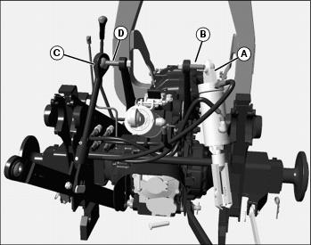
Installing and Removing 3-Point Hitch Equipped with Top and Tilt (Optional)
Installing Top Cylinder
1. Park machine safely. (See Parking Safely in the SAFETY section.)
2. Remove capscrews (A) and washers (B) from seat cables (C) on rockshaft housing.
4. Place top cylinder support bracket (D) on top of seat cables (C) on rockshaft housing.
5. Install capscrew (A) through support bracket and seat cables.
6. Tighten to 110 N·m (80 lb-ft).
7. Align base end of top cylinder (E) with mounting bracket holes (F).
· Choose top, middle or bottom set of holes based upon weight of intended load.
8. Fasten with attaching pin and quick-lock pin (G).
9. Align support bar (H) with support bracket.
10. Fasten with drilled pin and spring locking pin (I).
Installing Lift Link and Tilt Cylinder
1. Install base end of tilt cylinder (A) onto right rockshaft arm pin (B).
2. Fasten with quick-lock pin.
3. Install lift link (C) onto left rockshaft arm pin (D).
4. Fasten with quick-lock pin.
Installing Draft Links and Anti-Sway Links
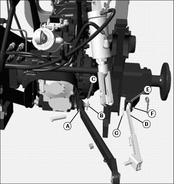
1. Install draft link (A) onto pin (B) on each side of transaxle.
2. Fasten each draft link with a quick-lock pin (C).
3. Locate anti-sway link (D) into mounting bracket (E) on each side of subframe.
4. Fasten anti-sway link to each bracket using drilled pin (F) and wire locking ring (G).
Picture Note: Right side installation.
5. Attach the rod end (H) of the tilt cylinder to the draft link.
6. Fasten with drilled pin (I), stop brackets (J), and spring locking pin (K).

Picture Note: Left side installation.
7. Raise draft link and align lift link clevis (L) with draft link hole (M).
8. Install float pin (N) through clevis and draft link from inside to outside in vertical position.
9. Install bushing (O) onto float pin in vertical position.
10. Fasten with quick-lock pin (P).
11. Install anti-sway link stud (Q) in draft link hole (R).
12. Install and tighten nut (S).
13. Repeat procedure for anti-sway link on opposite side of machine.
IMPORTANT: Avoid damage! The anti-sway links must be adjusted to hold the implement in place as close to the centerline as possible. Do not use the anti-sway links in the float position. |
14. Use left and right anti-sway links to adjust 3-point hitch implement side-to-side sway.
Connecting Hoses
1. Connect top cylinder rod end hose to quick coupler (A) and the cylinder base end hose to quick coupler (B).
2. Connect tilt cylinder rod end hose to quick coupler (C) and the cylinder base end hose to quick coupler (D).
3. Check operation of top cylinder and tilt cylinder to dual SCV handle movement.
Removing
1. Park machine safely. (See Parking Safely in the SAFETY section.)
2. Relieve quick coupler hydraulic pressure.
3. Disconnect the hydraulic hoses from the quick couplers and install dust caps.
4. Remove anti-sway links from subframe mounting holes.
5. Install drilled pins and locking rings into anti-sway links for storage.
6. Remove lift link and tilt cylinder from rockshaft arm pins.
7. Install quick-lock pins into rockshaft arm pins for storage.
8. Remove draft links from pins on each side of transaxle.
9. Install quick-lock pins into transaxle pins for storage.
10. Remove top cylinder and support bar.
11. Install attaching pin and quick-lock pin into top cylinder for storage.
Installing Loader Multi-Purpose Bucket (Optional)
1. Park machine safely. (See Parking Safely in the SAFETY section.)
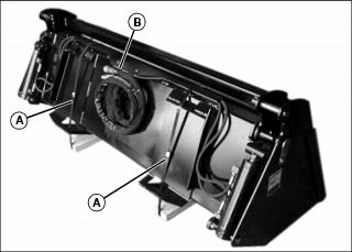
2. Remove banding (A) from around bucket.
NOTE: Only remove the tie strap(s) needed to allow the hoses to reach the quick couplers on the boom and allow the bucket to fully tilt and roll-back.
3. Remove tie strap (B) securing hoses.
4. Attach bucket to loader boom using QUIK-TATCH instructions in this section.
5. Connect hoses to corresponding quick couplers on loader boom.