
Assembly
Identify Parts
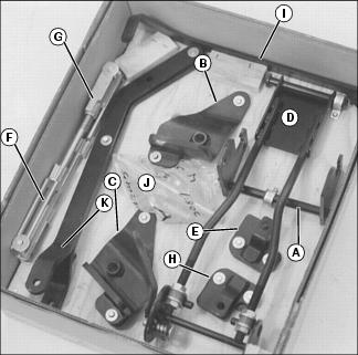
Following parts are included in crate:
• Deck with rear wheels installed upside down on deck.
Following parts are included in the box of Lift System Parts:
Install Rear Wheels
1. Remove hardware securing wheels to mower.
2. Remove wheels, rotate and install in proper position on mower.
3. Install hardware to secure wheels to mower.
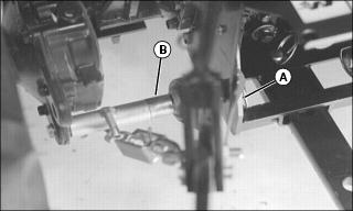
Install PTO Shaft On Gearbox
1. Remove cover from gearbox shaft.
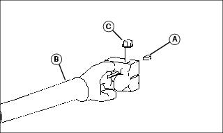
2. Install key (A) in slot in gearbox shaft. Coat shaft with MPG-2 lubricant or equivalent.
3. Install PTO shaft (B) on gearbox.
4. Fasten with one M10x50 hex head bolt (C). Tighten to 75 N•m (55 lb-ft).
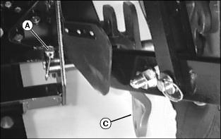
Attach Mower Mounting Bracket
NOTE: A front attaching support kit or hood guard is also required to install the front hitch.
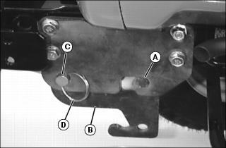
1. Place welded pin (A) of the mower mounting bracket (B) in the rear of slot on the attaching support bracket or hood guard.
2. Slide pin (C) all the way through front hole and attach with locking rings (D) on each end.
Attach Rear Draft Arm Support Brackets
NOTE: The right draft arm bracket has a wider space to allow the right rear draft arm and sway bar to be connected to the bracket.
Spacer plates are not required with loader arms installed.
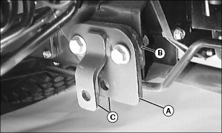
Picture Note: Right draft arm bracket shown.
1. Connect each draft arm bracket (A) and spacer plate (B) to the frame with M12x40 hex head bolts and M12 flanged locknuts.
Attach Lift Arm Brackets
1. Remove quick-lock pins (A) and slide shaft inward enough to remove bushing (B) from rear lift arms (one on each side).
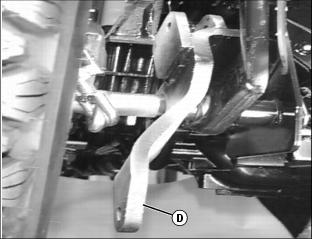
2. Install right rear lift arm bracket (C) and the left rear lift arm bracket (D) on the left side, in place of the bushing just removed.
3. Slide shaft back in place and install quick-lock pin (A).
Assemble Lift Links to Right and Left Draft Arms
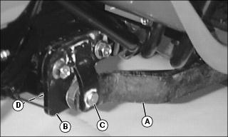
1. Connect the left draft arm (A) to the rear draft support bracket (B), using a draft arm pin (C) and a locking ring (D).
NOTE: Install two washers if space allows to minimize clearance.
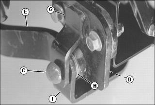
2. Connect the right draft arm (E) and the end of the sway bar (F) to the draft arm bracket (G). Place one washer (H) (or two if space allows) between the sway bar and the right draft arm. Secure using draft arm pin (C) and locking ring (D).
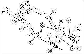
3. Attach the sway bar (F) to the left draft arm (A) using an M12x40 hex head bolt (G) and M12 flanged locknut.
4. Attach each clevis (H) to draft arms (A and E) using draft arm pins (C) and cotter pins.
NOTE: The lift links come preset at 50 cm (20 in.), but need to be adjusted to the upstop.
Do not bend cotter pin at this time.
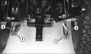
5. Fasten each lift link (I) to the mower lift arm brackets (J) using a draft arm pin (C), washers each side and a cotter pin.