
Installing
Preparing the Machine
NOTE: Read and complete the Assembly Section of this operator manual if installing the attachment for the first time.
Required Equipment
Machine Setup
• Check the tire pressures for machine to ensure proper cutting height.
Installing Mower
1. Park machine safely. (See Parking Safely in the Safety section.)
NOTE: Do not discard mid-PTO shield. Install shield when attachment driveshaft is removed.
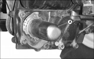
2. Turn PTO shield (A) counter-clockwise to remove from mid-PTO shaft.
NOTE: Turn both front wheels using following procedure.
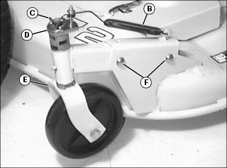
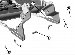
3. Remove spring (B) from each front wheel assembly by removing quick-lock pin (C), and lifting the tension bracket (D) off pivot shaft.
4. Remove left front wheel assembly (E) by removing the spring locking pins and drilled pins (F).
NOTE: Turn both rear wheels using following procedure.
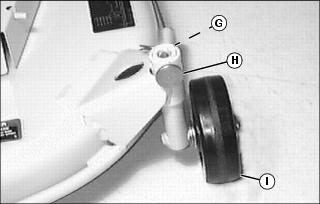
5. Remove locking ring (G) and drilled pin (H).
6. Turn rear wheel (I) sideways.
7. Install drilled pin and spring locking pin.
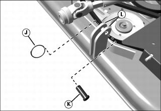
8. Remove locking rings (J) and drilled pins (K) from rear mounting brackets (L) on both sides of the mower deck.
9. Turn steering wheel fully to the left.
11. Pull depth control rockshaft lever to rear to fully raise lift arms.
13. Roll mower under tractor from right side of machine.
14. Push rockshaft control lever forward to lower lift arms.
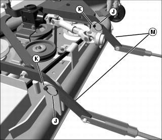
15. Install both rear draft arms (M) between the rear mounting brackets on the mower deck.
16. Secure the rear draft arms to the mower deck mounting brackets using drilled pins (K) and locking rings (J).
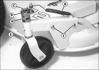
17. Install each front wheel assembly (E) using spring locking pins and drilled pins (F).
18. If the spacers (N) were removed, install spacers to match the number and position on the other front wheel.
19. Rotate the wheel as shown.
20. Install spring (B) by installing tension bracket (D) on the pivot shaft.
21. Install quick-lock pin (C).
22. Rotate rear wheels to mowing position.
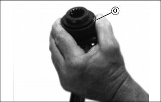
23. Pull back and hold the locking collar (O) on the driveshaft coupler.
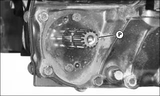
24. Push driveshaft on the mid-PTO shaft (P) until the coupler stops.
25. Pull the driveshaft until the locking collar (O) locks in place.
Connect Front Draft Arm Assembly
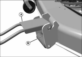
1. Install front draft arm assembly (A) in the slot in the bracket (B) on front of mower deck.
2. Position mower draft arm assembly, so that the round side plates are inside the mounting bracket on the front of the tractor, and the lever is outside the bracket.
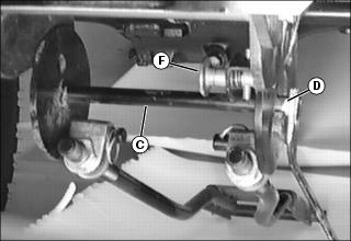
3. Install pivot shaft (C), making sure each end (D) is secure in the slot of the mounting bracket.
NOTE: Spring loaded pin must snap in hole.
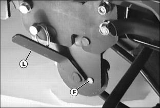
4. Pivot lever (E) to rear until pin (F) snaps in place.
6. Raise mower by pulling depth control rockshaft lever rearward.
Adjusting Deck Lift Height
1. Park machine safely. (See Parking Safely in the Safety section.)
3. Raise mower by pulling depth control rockshaft lever rearward.
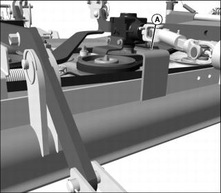
5. Check the distance between the top of the upstop (A) at the rear of the mower deck and the machine frame. Clearance should be 3 mm (1/8 in.) or less. Adjust as needed.
6. Adjust upstop-to-frame clearance:
a. Push rockshaft lever forward to fully lower lift arms.
b. Remove cotter pins (B) and washers (C).
NOTE: Clockwise will shorten links and raise deck.
d. Rotate each turnbuckle (E) equal amounts on of the lift link, until the 3 mm (1/8 in.) is obtained between the upstop and the frame.
f. Install washers (C) and cotter pins (B).