
Service Electrical
Battery Statement
Service Battery Safely

Removing and Installing Battery
Removing:
1. Park the machine safely. (See Parking Safely in the SAFETY section.)
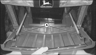
3. Pull out on grille and disconnect two springs (A) to remove grille.
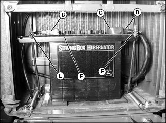
4. Disconnect black negative (-) cable (B) from battery first.
5. Slide red positive terminal cover (C) back and disconnect red positive (+) cable (D).
· Remove hex nuts (E) and bracket (F).
Installing:
1. Install battery into machine.
2. Check manifold caps to be sure vent holes are open.
3. Install battery hold-down assembly. Do not overtighten.
4. Connect positive (+) cable to battery first, then negative (-) cable.
5. Apply petroleum jelly on battery terminals to help prevent corrosion.
Cleaning Battery and Terminals
1. Park the machine safely. (See Parking Safely in the SAFETY section.)
4. Disconnect negative (black) cable from battery first.
5. Disconnect positive (red) cable from the battery.
6. Wash battery with solution of four tablespoons of baking soda to one gallon of water. Be careful not to get the soda solution into the cells.
7. If battery is very dirty, remove battery.
8. Clean battery case, terminals, cable ends, hold-down, and tray.
9. Rinse all parts with clean water. Let dry.
10. Clean terminals and battery cable ends with wire brush until bright.
12. Connect positive (red) cable to battery first, then the negative (black) cable.
13. Apply petroleum jelly on battery terminals to help prevent corrosion.
14. Install battery hold-down retainer and tighten hardware.
Checking Battery Electrolyte Level
NOTE: Add only distilled water to replace normal electrolyte loss.
1. Park the machine safely. (See Parking Safely in the SAFETY section.)
2. Remove battery from machine and set it on a level surface.
3. Remove battery cell caps. Make sure cap vents are not plugged.
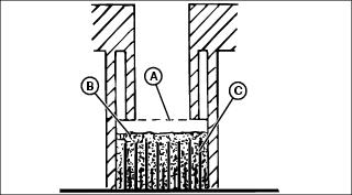
4. Check electrolyte level. Electrolyte (A) should be approximately halfway between bottom of filler neck (B) and top of plates (C).
IMPORTANT: Avoid damage! Do not overfill battery. Electrolyte can overflow when battery is charged and cause damage. |
5. Add only distilled water if necessary.
Using Booster Battery

1. Connect positive (+) booster cable to booster battery (A) positive (+) post (C).
2. Connect the other end of positive (+) booster cable to the disabled machine battery (B) positive (+) post (D).
3. Connect negative (-) booster cable to booster battery negative (-) post (E).
4. Connect the other end (F) of negative (-) booster cable to a metal part of the disabled machine frame away from battery.
5. Start the engine of the disabled machine and run machine for several minutes.
6. Carefully disconnect the booster cables in the exact reverse order: negative cable first and then the positive cable.
Replacing Fuses
IMPORTANT: Avoid damage! The electrical system may be damaged if incorrect replacement fuses are used. Replace the bad fuse with a fuse of the same amp rating. |
1. Park machine safely. (See Parking Safely in the SAFETY section.)
3. Remove left side engine panel.
4. Pull cover (A) off fuse holder.
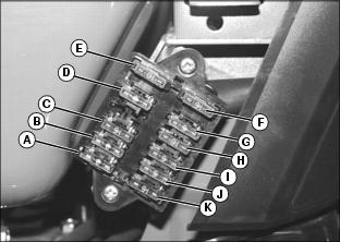
A - 3 Amp Fuse - 1st position - Seat Switch
B - 3 Amp Fuse - 2nd position - Control Box, Fuel Solenoid
C - 15 Amp Fuse - 3rd position - Warning and Turn Lights and Control Panel Lights
D - 3 Amp Fuse - 5th position - Spare
E - 10 Amp Fuse - 6th position - Spare
F - 15 Amp Fuse - 7th position - Spare
G - 5 Amp Fuse - 8th position - Spare
H - 10 Amp Fuse - 9th position - Flood Lights
I - 5 Amp Fuse - 10th position - Warning Lights
J - 5 Amp Fuse - 11th position - Tail Light Switch
K - 15 Amp Fuse - 12th position - Headlights
6. Pull defective fuse from socket.
9. Install left side engine panel.
Replacing Headlight Bulb
1. Park machine safely. (See Parking Safely in the SAFETY section.)
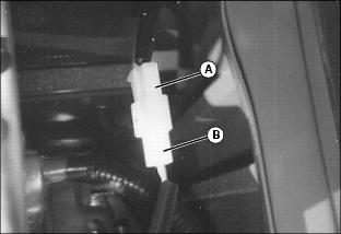
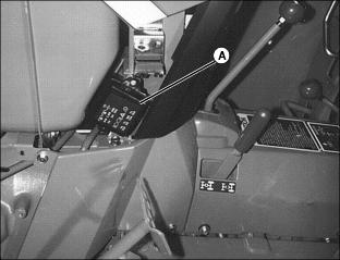
3. Disconnect wiring harness (A) from headlight bulb connector (B).
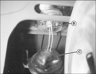
4. Pull back rubber protector (C) from assembly. Rotate headlight bulb assembly (D) left 1/3 turn and remove from headlight housing socket.
5. Install new headlight bulb assembly into housing socket and rotate right 1/3 turn into a locked position.
6. Replace rubber protector (C).
7. Connect wiring harness to headlight bulb connector.
Replacing Taillight Bulb
NOTE: Taillight can be serviced by removing the rear assembly lens.
1. Park machine safely. (See Parking Safely in the SAFETY section.)
2. Remove two screws (A) and lens from the taillight assembly.
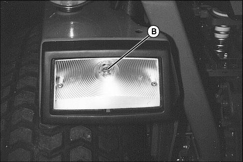
3. Push and turn bulb (B) to remove.
Replacing Warning Light Bulb
1. Park machine safely. (See Parking Safely in the SAFETY section.)
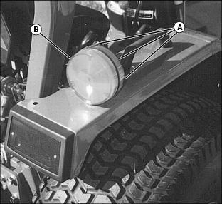
2. Remove three screws (A) and lens (B) from the warning light assembly.
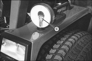
3. Push down and rotate bulb (C) to remove.
Replacing Instrument Panel Light Bulb
1. Park machine safely. (See Parking Safely in the SAFETY section.)
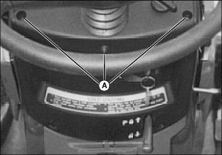
3. Remove three screws (A) from console panel below instrument panel.
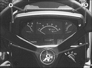
4. Remove six instrument panel screws (B).
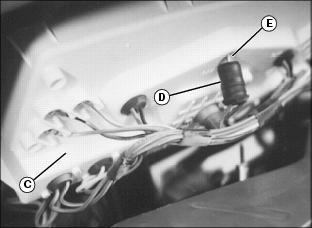
5. Carefully raise instrument panel (C).
6. Identify defective bulb location and remove bulb holder (D) from instrument panel socket.
7. Pull defective bulb from socket. Do not twist.
8. Push new bulb (E) into socket.
9. Install bulb holder into instrument panel.
Adjusting Head Lights
1. Park machine safely on a level surface at least 5m (15ft.) away from a flat vertical surface. (See Parking Safely in the SAFETY section.)
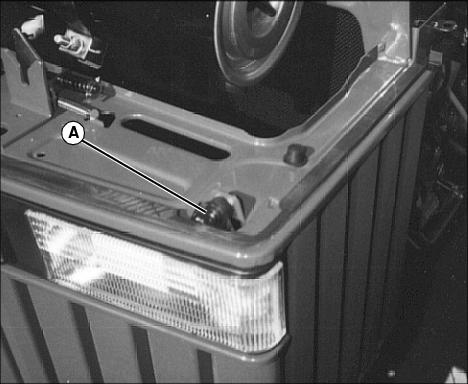
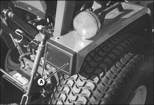
4. Turn head light screw (A) to adjust light beam up or down.
5. Repeat procedure for opposite headlight if adjustment is required.