
Service Miscellaneous
Using Proper Fuel (Diesel)
Use the proper diesel fuel to help prevent decreased engine performance and increased exhaust emissions. Failure to follow the fuel requirements listed below can void your engine warranty.
Contact your local fuel distributor for properties of the diesel fuel in your area.
In general, diesel fuels are blended to satisfy the low temperature requirements of the geographical area in which they are marketed.
Diesel fuels specified to EN 590 or ASTM D975 are recommended.
In all cases, the fuel shall meet the following properties:
If a fuel of low or unknown lubricity is used, addition of John Deere PREMIUM DIESEL FUEL CONDITIONER at the specified concentration is recommended.
· Diesel fuel quality and fuel sulfur content must comply with all existing emissions regulations for the area in which the engine operates.
· Sulfur content less that 0.05% (500 ppm) is recommended for best performance.
· Diesel fuel sulfur content greater than 0.5% (5000 ppm) should not be used.
IMPORTANT: Avoid damage! Do not mix diesel engine oil or any other type of lubricating oil with diesel fuel. |
Handling and Storing Diesel Fuel
Do not smoke while you fill the fuel tank or service the fuel system. |
· Fill the fuel tank at the end of each day's operation to prevent water condensation and freezing during cold weather.
IMPORTANT: Avoid damage! The fuel tank is vented through the filler cap. If a new cap is required, always replace it with an original vented cap. |
· When fuel is stored for an extended period or if there is a slow turnover of fuel, add a fuel conditioner to stabilize the fuel and to prevent water condensation. Contact your fuel supplier for recommendations.
Filling Fuel Tank
Fill fuel tank at the end of each day's operation to prevent condensation and freezing during cold weather.
1. Park machine safely. (See Parking Safely in the SAFETY section.)
3. Remove any trash from area around fuel tank cap.
4. Remove fuel tank cap slowly to allow any pressure built up in tank to escape.
5. Fill fuel tank only to bottom of filler neck.
Raising and Lowering Hood
Raising
1. Park machine safely. (See Parking Safely in the SAFETY section.)
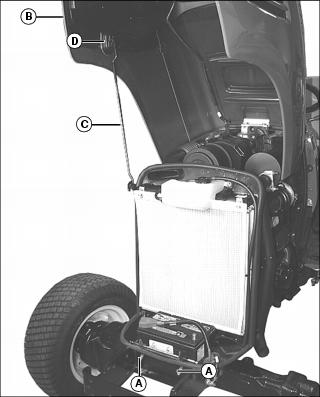
2. Lift hood release levers (A).
3. Raise hood (B), and raise support rod (C) to secure into bracket hole (D).
Lowering
1. Lift hood slightly to remove weight from support rod (C).
2. Release support rod from bracket hole (D), and lower support rod to latch on machine frame.
4. Push down on front of hood to lock the latch.
Checking Wheel Bolts and Hardware
When machine is new or anytime wheel hardware is loosened, tighten all bolts after one hour of operation and every four hours thereafter until proper torque values are maintained.
Tightness of wheel hardware must be maintained according to service interval recommendations. Check wheel bolt tightness as follows:
Front Wheel Bolts
Tighten front wheel bolts alternately to 140 N·m (103 lb-ft).
Rear Wheel Bolts
Tighten rear wheel bolts alternately to 140 N·m (103 lb-ft).
Checking Tire Pressure
2. See tire pressures in SPECIFICATIONS.
3. Check tire pressure with an accurate gauge.
4. Add or remove air, if necessary
Selecting Front Tire Rolling Direction
· Use a safe lifting device and support machine securely on jack stands. · Block front and rear of wheel not raised to prevent machine movement. |
Machines equipped with directional type tires (such as bar tires) have directional arrows located on the tire sidewall. Under most conditions, tires should be installed with the directional arrow pointing in the direction of travel.
If machine is mainly used for loader operations, lug direction may be reversed to increase tire life and improve traction while backing out of dirt piles.
Move wheel from one side of machine to the other.
Changing Wheel Spacing and Tread Width
The front and rear wheels can be mounted in wide or narrow positions to increase or decrease wheel spacing. To provide best stability, operate machine with rear wheels mounted in the wide tread position whenever possible.
· Use a safe lifting device and support machine securely on jack stands. · Block front and rear of wheel not raised to prevent machine movement. |
IMPORTANT: Avoid damage! Always make sure tires rotate in proper direction. Arrows on sidewall should point in direction of forward rotation. |
Front Wheel Positions:
· Wide position - Install wheel with valve stem to the inside.
· Narrow position - Install wheel with valve stem to the outside.
Rear Wheel Positions:
· Wide position - Install wheel with valve stem to the outside.
· Narrow position - Install wheel with valve stem to the inside.
The mounting flanges on the rear rims are closer to one edge of the rim than the other, allowing the inner wheels to be mounted in different positions. By changing this position of the wheel on the rim, up to eight different tread widths can be achieved on some machines.
Various positions cannot be used because the tires would strike the fenders. Certain other positions may result in equal tread widths.
The front wheel spacing can be adjusted to eight different tread widths by reversing the front wheels and by extending the front axle.
Tread width is measured from centerline-to-centerline of each tire.
Mounting Guidelines
· To keep tire rotation in the proper direction when wheels are reversed without removing tires from rims, move each wheel to the opposite side of the machine.
· Rims can be attached to either side of wheel.
· Mounting flanges on rim are closer to one edge of rim.
· Tread width can be changed by turning the wider side in or out.
· To keep tire rotation in the proper direction, move each rim to opposite side of machine, rather than turning the rims around.
· Dished wheels can be reversed.
· Tighten all bolts to specifications.
Rear Tire Tread Width Dimensions
Front Tire Tread Width Dimensions
* Do not install tires with chains in this position.
Checking and Adjusting Toe-In
1. Stop machine on a firm, level surface.
2. Disengage MFWD if equipped.
3. Turn steering wheel so front wheels are pointing straight ahead.
4. Park machine safely. (See Parking Safely in the SAFETY section.)
Checking Toe-In
NOTE: If front axle is equipped with bar tires, use an outside bar of each tire or an inside bar of each tire for marking the center line.
1. Mark the center line of each tire at hub height and to the front of the axle using chalk.
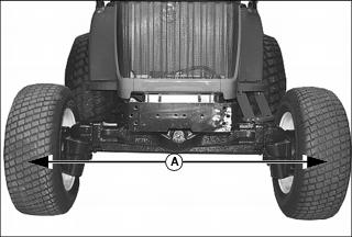
2. Measure distance (A) between the center lines of each tire. Record the measurement.
3. Drive machine forward or rearward slightly until chalk mark moves 180° to the rear of the axle.
4. Park machine safely. (See Parking Safely in the SAFETY section.)
5. Measure distance (A) again between the chalk marks. Record the measurement.
6. Determine the difference between front and rear measurements. Distance (A) may be larger at front or rear measurement but should not exceed 3 mm (1/8 in.). Adjust toe-in if necessary.
Adjusting Toe-In
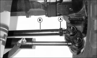
1. Loosen jam nuts (A) on both tie rods.
2. Rotate tie rods (B) clockwise or counterclockwise to adjust the amount of toe-in. Adjust tie rods until toe-in measurement is within correct specification.
· Rotating threaded rod in 1/2 turn increments equals 1.5 mm (1/16 in.).
3. Tighten jam nuts to 120 N·m (88 lb-ft).
4. Check toe-in setting. Repeat procedure if further adjustment is required.
Cleaning and Repairing Plastic Surfaces
Your authorized dealer has the professional materials needed to properly remove surface scratches from any plastic surfaces, do not attempt to paint over marks or scratches in plastic parts.
1. Rinse hood and entire machine with clean water to remove dirt and dust that may scratch the surface.
2. Wash surface with clean water and a mild liquid automotive washing soap.
3. Dry thoroughly to avoid water spots.
4. Wax the surface with a liquid automotive wax. Use products that specifically say "contains no abrasives."
5. Buff applied wax by hand using a clean, soft cloth.
Cleaning and Repairing Metal Surfaces
Cleaning:
Follow automotive practices to care for your vehicle painted metal surfaces. Use a high-quality automotive wax regularly to maintain the factory look of your vehicle's painted surfaces.
Repairing Minor Scratches (surface scratch):
1. Clean area to be repaired thoroughly.
2. Use automotive polishing compound to remove surface scratches.
3. Apply wax to entire surface.
Repairing Deep Scratches (bare metal or primer showing):
1. Clean area to be repaired with rubbing alcohol or mineral spirits.
2. Use paint stick with factory-matched colors available from your authorized dealer to fill scratches. Follow directions included on paint stick for use and for drying.
3. Smooth out surface using an automotive polishing compound. Do not use power buffer.