Assembly
Assembly and Installation
Some parts are used during backhoe assembly, others are used during installation on tractor.
Parts (Model 448)
Parts (4500-4710 Tractor Mounting)
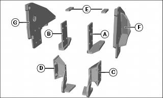
Parts (4510-4720 Tractor Mounting)
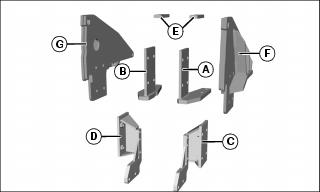
Parts (Model 447)
Parts (4200-4410 Tractor Mounting)
Parts (3120-3720 Tractor Mounting)*
NOTE: Parts for model 447 and 448.
Remove Backhoe From Pallet
1. Position pallet on level ground where tractor can be backed up for installation.
2. Remove plastic wrap from seat. Remove seat if not installed.
3. Remove stabilizers or stabilizer legs from pallet.
4. Remove bags covering ends of hydraulic hoses.
5. Remove any bolts and plates securing other parts to pallet. Backhoe may remain on pallet for stability until tractor installation.
6. Backhoe may remain on pallet for stability until tractor installation.
Assemble Backhoe
NOTE: Large frame adapter (tractor models 4500-4710, 4120-4720) or medium frame adapter (tractor models 4200-4410, 3120-3720) is required for model 448 backhoe.
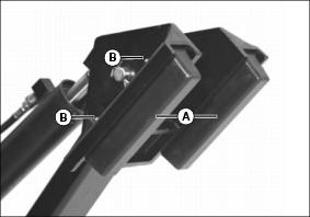
1. Install adapter (Model 448 only):
a. Install adapter (A) on backhoe frame with eight 3/4x2 in. capscrews (B), sixteen hardened washers, and eight locknuts.
b. Tighten all cap screws to 375 N•m (280 lb-ft).
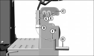
2. Loosely install latch plates (C) and cables (D) on outside of backhoe hooks with four 1/2 x 1-1/4 in. cap screws (E), lockwashers, and washers. Center the slots in the latch plates on the cap screws before tightening.
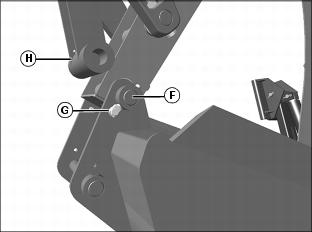
3. Install retainer rings (F) in L-pins (G) and cables as shown.
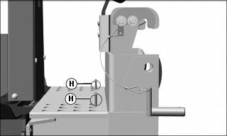
4. Store hitch pins (H) for L-pins in storage holes on floor of operator’s station as shown.
Install Stabilizers

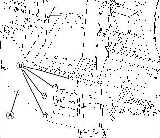
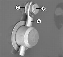
NOTE: Pivot pins on backhoe are installed with either cotter pins or retainers (A). Retainer is installed in pivot pin with bolt (B), 11/32-in. washer (C), and 5/16-in. locknut.
1. Remove pivot pins stored in stabilizers.
2. Remove retainers securing pivot pins to backhoe.
3. Remove pivot pins securing cylinders to backhoe, and remove cylinders.
NOTE: Lubricate all pivot pins before installation.
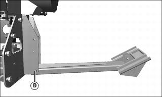
4. Install both stabilizers on backhoe with pivot pin (D) as shown. Install cotter pins or retainers in pivot pins.
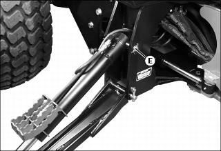
5. Install both cylinders on backhoe with pivot pin (E) as shown. Route all hydraulic hoses above the pivot pins (E).
6. Install cotter pins or retainers in pivot pins.
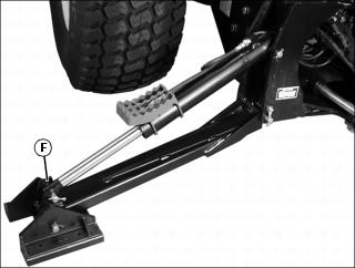
7. Install both cylinders on stabilizers with pivot pins (F) as shown.
8. Install cotter pins in pivot pins.
9. Lubricate all grease fittings and pivot points before operating backhoe.
Install Bucket
NOTE: Lubricate all pivot pins before installation.
NOTE: Pivot pins on backhoe are installed with either cotter pins or retainers (A). Retainer is installed in pivot pin with bolt (B), 11/32 in. washer (C), and 5/16 in. locknut.
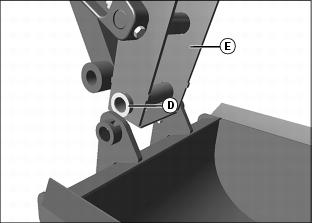
1. Grease both sides of two 1-1/32 x 1-1/2 in. washers (D) and install between bucket and dipperstick (E) on both sides of dipperstick if needed.
2. Install pivot pin (F) through bucket, washers, and dipperstick.
3. Install two retainers (G) in pivot pin with hardware.
4. Remove shipping wire holding link (H) to dipperstick.
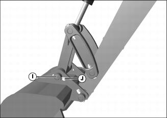
5. Pivot the bucket back and install pivot pin (I) through bucket and link. Install two 1-1/32 x 1-1/2 in. washers between bucket and link if needed.
6. Install two retainers (J) in pivot pin with hardware.
7. Lubricate all grease fittings and pivot points before operating backhoe.
Installing Slow Moving Vehicle (SMV) Sign
NOTE: Use the SMV sign when transporting the backhoe on roads.
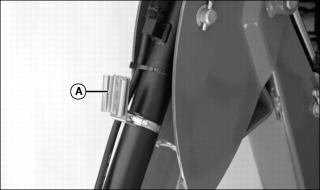
1. Remove SMV sign from tractor, and install into bracket (A) on the backhoe bucket cylinder.
Install Operator Seat (448)
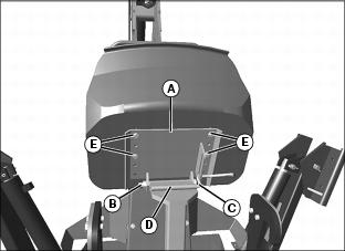
1. Install plate (A) on bracket with 1/2 x 6-1/2 in. cap screw (B) and nut. Tighten until slight drag is felt when pivoting plate.
2. Lower plate and install handle (C) through slotted area on plate (A) and welded rod (D) on seat post. Secure end with washer and cotter pin.
3. Position where desired and install seat on plate with four 5/16 x 3/4 in. cap screws (E) and lockwashers.