
Preparing Vehicle
All Tractor Models
1. Park machine safely. (See Parking Safely in SAFETY.)
2. If tractor model 4120-4720 has R4 tires installed, the mid-mount mower deck must be removed. On tractors with other tires installed:
a. Raise mower deck and install transport lock.
b. Remove mower lift links from rockshaft draft links.
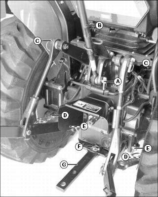
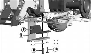
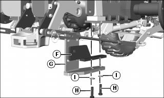
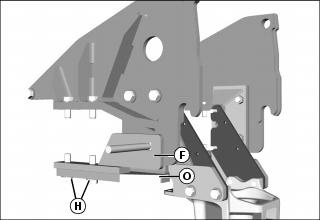
3. Remove 3-point hitch and drawbar:
a. Remove locking pins (A) and center link (B).
b. Remove locking pins (C), (D), and (E), and remove links on both sides.
c. Disassemble links as needed and install locking pins in links for storage.
IMPORTANT: Avoid damage! Failure to remove drawbar from tractor will result in damage to tractor, backhoe, or both. |
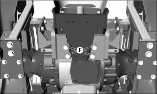
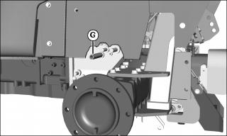
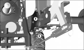
d. Remove locking pin (F) and drawbar (G). Install pin in drawbar to store.
• Use a safe lifting device and support machine securely on jack stands. • Block front and rear of wheel not raised to prevent machine movement. |
4. Mount rear wheels in widest tread width position.
NOTE: If removing rear wheels to change tread width, leave wheels off tractor until RSA mounting plates are installed.
5. Install rockshaft assist (RSA) mounting plates.
6. Inflate tires to maximum pressure recommended by tire manufacturer.
7. Install Tall Folding Roll Over Protection System (ROPS).
10. Follow machine operator’s manual instructions to check hydraulic fluid level.
Install Rockshaft Assist (RSA) Mounting Plates (4500, 4600, 4510-4710, 4120-4720)
All Tractor Models 4500-4600, Early Tractor Models 4510-4710 (All Tractors)
NOTE: Drawbar assemblies are welded on early tractor models 4510-4710. Late models have cast iron drawbar assemblies.
• Use a safe lifting device and support machine securely on jack stands. • Block front and rear of wheel not raised to prevent machine movement. |
NOTE: Removing rear wheels and fenders is not required but makes installation easier.
1. Raise rear of tractor and support rear axles with jack stands.
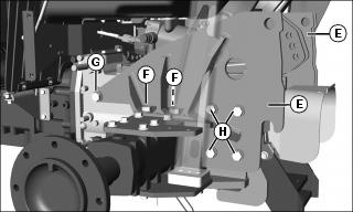
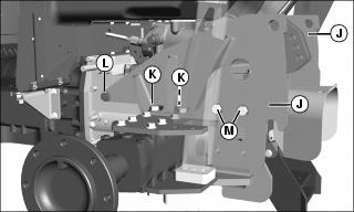
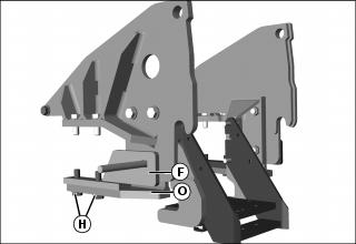
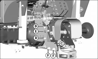
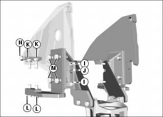
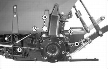
3. Remove four cap screws (A) and washers in sides of drawbar hitch support.
4. Remove four cap screws (B) and lock washers from bottom of drawbar hitch support.
5. Loosely install both hook weldments (C) on drawbar hitch support with four M12x55 cap screws (D), and four 1/2 in. washers.
6. Loosely install two M12 nuts (E), and two 1/2 in. washers on tractor studs.
7. Install four new M14x45 cap screws (F) and 9/16 in. washers in hook weldments. Tighten to 40 N•m (30 lb-ft).
8. Tighten M12x55 cap screws (D) and M12 nuts (E) to 40 N•m (30 lb-ft).
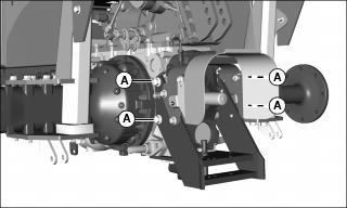
9. Install hex spacer (G) on 16mm stud on both sides of transaxle. Tighten to 163 N•m (120 lb-ft).
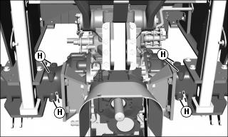
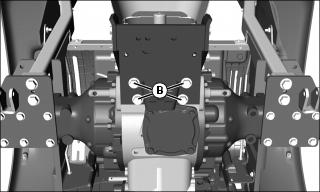
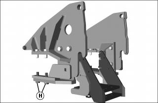
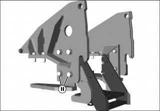
10. Use a M16x2 tap to clean the M16 tapped holes (H) in both top and bottom of the rear axles on both sides of tractor.
All Tractor Models 4500-4600, Early Tractor Models 4510-4710 (Tractors Without Mid-Mount Lift Assemblies Installed)
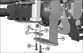
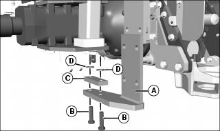
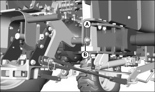
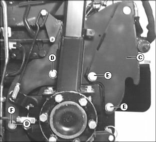
1. Install both mount weldments (A) in bottom of rear axle with two M16x60 cap screws (B), spacers (C), and 5/8 in. washers (D). Tighten to 40 N•m (30 lb-ft).
NOTE: LH side RSA mounting plate has a large hole to permit access to the transaxle oil filter tube.
Picture Note: Rear fenders removed in picture.
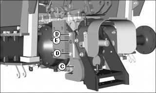
2. Install RSA mounting plates (E) onto mount weldments from rear of tractor. Avoid pinching electrical wires. Loosely install two M16x45 cap screws (F) and 5/8 in. washers in both mount weldments.
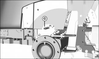
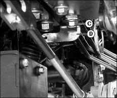
3. Loosely install one M16x45 cap screw (G) and 5/8 in. washer in both RSA mounting plates and hex spacers.
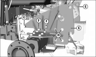
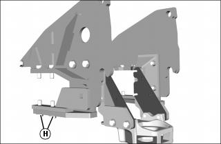
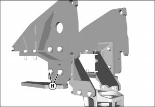
4. Loosely install four M16x60 cap screws (H) and washers in both RSA mounting plates.
IMPORTANT: Avoid damage! Proper tightening sequence is critical in achieving maximum clamping forces. Do not overtighten the cap screws. Damage to the transaxle case will result. |
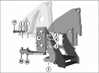
5. Tighten hardware on both sides in the following order:
a. Tighten the four M14x45 cap screws (I) in bottoms of hook weldments to 215 N•m (158 lb-ft).
b. Tighten the four M12x55 cap screws (J) and two M12 hex nuts (K) to 95 N•m (70 lb-ft).
c. Tighten the four M16x45 cap screws (L) installed on the top of the rear axle to 258 N•m (190 lb-ft).
d. Tighten the four M16x60 cap screws (M) installed on the bottom of the rear axle to 258 N•m (190 lb-ft).
e. Tighten the eight M16x60 cap screws (N) installed in the RSA mounting plates to 217 N•m (160 lb-ft).
f. Tighten the two M16x45 cap screws (O) installed in the threaded hex spacers to 163 N•m (120 lb-ft).
6. Install fenders if removed.
7. Mount rear wheels in widest tread width position. See your machine operator’s manual or technical manual for wheel bolt torque.
8. Inflate tires to maximum pressure recommended by tire manufacturer.
9. Install Tall Folding Roll Over Protection System (ROPS).
12. Follow machine operator’s manual instructions to check hydraulic fluid level.
All Tractor Models 4500-4600, Early Tractor Models 4510-4710 (Tractors With Mid-Mount Lift Assemblies Installed)
1. Support the mower deck if installed.
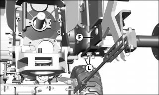
2. Remove the mower deck pivot plates:
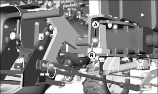
a. Remove and retain nut (A) and washer (B) from carriage bolt securing pivot plate to lift arm on both sides of tractor.

b. Tractor RH side only: Loosen ROPS bolt (C) and move spring bracket (D) out of the way.
c. Remove M16x40 cap screws (E) and pivot plate (F) [including carriage bolt, washer, and spacer] from both sides of tractor. Retain cap screws for use with mower deck if RSA mounting plates are removed.
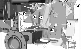
3. Install both mount weldments (G) and pivot plates (F) in bottom of rear axle with two M16x60 cap screws (H), and 5/8 in. washers (I). Tighten to 40 N•m (30 lb-ft).
4. Install RSA mounting plates (J) onto mount weldments from rear of tractor. Avoid pinching electrical wires. Loosely install two M16x45 cap screws (K) and 5/8 in. washers in both RSA mounting plates.
5. Loosely install M16x45 cap screw (L) and 5/8 in. washer in RSA mounting plate and hex spacer on both sides of tractor.
6. Loosely install two M16x60 cap screws (M) and washers in top two holes in both RSA mounting plates.
7. Remove two M16x60 cap screws (H) and washers securing mount weldments and pivot plates to bottom of left and right rear axle. Retain hardware for installation later.
8. Remove and retain each pivot plate using a hammer and a punch.
9. Install two M16x60 cap screws (N) and 5/8 in. washers in bottom two holes in both RSA mounting plates. Tighten to 217 N•m (160 lb-ft).
10. Install original M16x155 carriage bolt in square hole of pivot plate.
11. Install pivot plate (F) between mount weldment (O) and bottom of tractor rear axle. Loosely install two M16x60 cap screws (H) and 5/8 in. washers removed earlier.
IMPORTANT: Avoid damage! Proper tightening sequence is critical in achieving maximum clamping forces. Do not overtighten the cap screws. Damage to the transaxle case will result. |
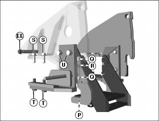
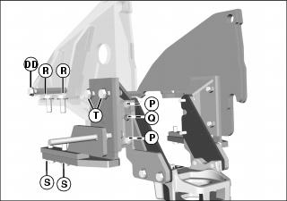
a. Tighten the four M14x45 cap screws (P) in bottoms of hook weldments to 215 N•m (158 lb-ft).
b. Tighten the four M12x55 cap screws (Q) and two M12 hex nuts (R) to 95 N•m (70 lb-ft).
c. Tighten the four M16x45 cap screws (S) installed on the top of the rear axle to 258 N•m (190 lb-ft).
d. Tighten the four M16x60 cap screws (T) installed on the bottom of the rear axle to 258 N•m (190 lb-ft).
e. Tighten the top four M16x60 cap screws (U) installed in the RSA mounting plates to 217 N•m (160 lb-ft).
13. Install mower deck pivot plates on lift arms with original hardware:
a. Install one washer (V) on the M16x155 carriage bolt (W).
b. Insert carriage bolt through lift arm (X) and add bushing (Y).
c. Insert carriage bolt through plate (Z) and secure with washer (AA) and M16 nut (BB).

14. Tractor RH side only: Move spring bracket (CC) back to its original position and tighten ROPS bolt (DD) to 138 N•m (102 lb-ft).
15. Tighten the two M16x45 cap screws (EE) installed into the threaded hex spacers to 163 N•m (120 lb-ft).
16. Install fenders if removed.
17. Mount rear wheels in widest tread width position. See your machine operator’s manual or technical manual for wheel bolt torque.
18. Inflate tires to maximum pressure recommended by tire manufacturer.
19. Install Tall Folding Roll Over Protection System (ROPS).
22. Follow machine operator’s manual instructions to check hydraulic fluid level.
Late Tractor Models 4510-4710, All Tractor Models 4120-4720 (All Tractors)
NOTE: Drawbar assemblies are welded on early tractor models 4510-4710. Late models have cast iron drawbar assemblies.
• Use a safe lifting device and support machine securely on jack stands. • Block front and rear of wheel not raised to prevent machine movement. |
NOTE: Removing rear wheels and fenders is not required but makes installation easier.
1. Raise rear of tractor and support rear axles with jack stands.
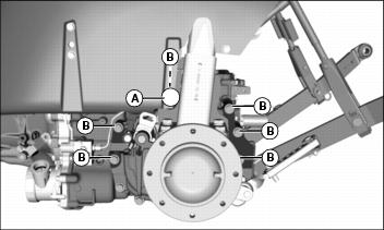
3. Remove four cap screws (A) and washers in sides of drawbar hitch support.
4. Remove four cap screws (B) on sides of drawbar assembly.
5. Loosely install both hook weldments (C) on drawbar hitch support with four M12x55 cap screws (D), and four 1/2 in. washers.
6. Loosely install two M12 nuts (E), and two 1/2 in. washers on tractor studs.
7. Loosely install four M14x60 cap screws (F) and four 9/16 in. hardened washers on sides of drawbar assembly.
8. Tighten M12x55 cap screws (D) and M12 nuts (E) to 40 N•m (30 lb-ft).
9. Tighten M14x60 cap screws (F) to 215 N•m (158 lb-ft).
10. Install hex spacer (G) on 16mm stud on both sides of transaxle. Tighten to 163 N•m (120 lb-ft).

11. Use a M16x2 tap to clean the M16 tapped holes (H) in both top and bottom of the rear axles on both sides of tractor.
Late Tractor Models 4510-4710, All Tractor Models 4120-4720 (Tractors Without Mid-Mount Lift Assemblies Installed)
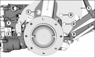
1. Install both mount weldments (A) in bottom of rear axle with two M16x60 cap screws (B), spacers (C), and 5/8 in. washers (D). Tighten to 40 N•m (30 lb-ft).
NOTE: LH side RSA mounting plate has a large hole to permit access to the transaxle oil filter tube.
Picture Note: Rear fenders removed in picture.
2. Install RSA mounting plates (E) onto mount weldments from rear of tractor. Avoid pinching electrical wires. Loosely install two M16x45 cap screws (F) and 5/8 in. washers in both mount weldments.
3. Loosely install one M16x45 cap screw (G) and 5/8 in. washer in both RSA mounting plates and hex spacers.
4. Loosely install four M16x60 cap screws (H) and washers in both RSA mounting plates.
IMPORTANT: Avoid damage! Proper tightening sequence is critical in achieving maximum clamping forces. Do not overtighten the cap screws. Damage to the transaxle case will result. |
5. Tighten hardware on both sides in the following order:
a. Tighten the four M12x55 cap screws (I) and two M12 hex nuts (J) to 95 N•m (70 lb-ft).
b. Tighten the four M16x45 cap screws (K) installed on the top of the rear axle to 258 N•m (190 lb-ft).
c. Tighten the four M16x60 cap screws (L) installed on the bottom of the rear axle to 258 N•m (190 lb-ft).
d. Tighten the eight M16x60 cap screws (M) installed in the RSA mounting plates to 217 N•m (160 lb-ft).
e. Tighten the two M16x45 cap screws (N) installed in the threaded hex spacers to 163 N•m (120 lb-ft).
6. Install fenders if removed.
7. Mount rear wheels in widest tread width position. See your machine operator’s manual or technical manual for wheel bolt torque.
8. Inflate tires to maximum pressure recommended by tire manufacturer.
9. Install Tall Folding Roll Over Protection System (ROPS).
12. Follow machine operator’s manual instructions to check hydraulic fluid level.
Late Tractor Models 4510-4710, All Tractor Models 4120-4720 (Tractors With Mid-Mount Lift Assemblies Installed)
NOTE: If tractor model 41-4720 has R4 tires installed, the mid-mount mower deck must be removed.
1. Support the mower deck if installed.
2. Remove the mower deck pivot plates:
a. Remove and retain nut (A) and washer (B) from carriage bolt securing pivot plate to lift arm on both sides of tractor.
b. Tractor RH side only: Loosen ROPS bolt (C) and move spring bracket (D) out of the way.
c. Remove M16x40 cap screws (E) and pivot plate (F) [including carriage bolt, washer, and spacer] from both sides of tractor. Retain cap screws for use with mower deck if RSA mounting plates are removed.
3. Install both mount weldments (G) and pivot plates (F) in bottom of rear axle with two M16x60 cap screws (H), and 5/8 in. washers (I). Tighten to 40 N•m (30 lb-ft).
4. Install RSA mounting plates (J) onto mount weldments from rear of tractor. Avoid pinching electrical wires. Loosely install two M16x45 cap screws (K) and 5/8 in. washers in both RSA mounting plates.
5. Loosely install M16x45 cap screw (L) and 5/8 in. washer in RSA mounting plate and hex spacer on both sides of tractor.
6. Loosely install two M16x60 cap screws (M) and washers in top two holes in both RSA mounting plates.
7. Remove two M16x60 cap screws (H) and washers securing mount weldments and pivot plates to bottom of left and right rear axle. Retain hardware for installation later.
8. Remove and retain each pivot plate using a hammer and a punch.
9. Install two M16x60 cap screws (N) and 5/8 in. washers in bottom two holes in both RSA mounting plates. Tighten to 217 N•m (160 lb-ft).
10. Install original M16x155 carriage bolt in square hole of pivot plate.
11. Install pivot plate (F) between mount weldment (O) and bottom of tractor rear axle. Loosely install two M16x60 cap screws (H) and 5/8 in. washers removed earlier.
IMPORTANT: Avoid damage! Proper tightening sequence is critical in achieving maximum clamping forces. Do not overtighten the cap screws. Damage to the transaxle case will result. |
a. Tighten the four M12x55 cap screws (P) and two M12 hex nuts (Q) to 95 N•m (70 lb-ft).
b. Tighten the four M16x45 cap screws (R) installed on the top of the rear axle to 258 N•m (190 lb-ft).
c. Tighten the four M16x60 cap screws (S) installed on the bottom of the rear axle to 258 N•m (190 lb-ft).
d. Tighten the top four M16x60 cap screws (T) installed in the RSA mounting plates to 217 N•m (160 lb-ft).
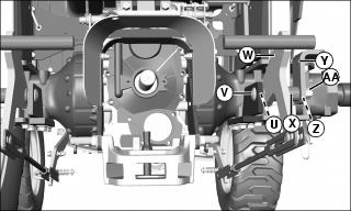
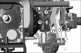
13. Install mower deck pivot plates on lift arms with original hardware:
a. Install one washer (U) on the M16x155 carriage bolt (V).
b. Insert carriage bolt through lift arm (W) and add bushing (X).
c. Insert carriage bolt through plate (Y) and secure with washer (Z) and M16 nut (AA).
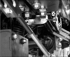
14. Tractor RH side only: Move spring bracket (BB) back to its original position and tighten ROPS bolt (CC) to 138 N•m (102 lb-ft).
15. Tighten the two M16x45 cap screws (DD) installed into the threaded hex spacers to 163 N•m (120 lb-ft).
16. Install fenders if removed.
17. Mount rear wheels in widest tread width position. See your machine operator’s manual or technical manual for wheel bolt torque.
18. Inflate tires to maximum pressure recommended by tire manufacturer.
19. Install Tall Folding Roll Over Protection System (ROPS).
22. Follow machine operator’s manual instructions to check hydraulic fluid level.
Install Rockshaft Assist (RSA) Mounting Plates (4200-4400, 4210-4410, 3120-3720)
Tractor Models 4200-4400, 4210-4410
• Use a safe lifting device and support machine securely on jack stands. • Block front and rear of wheel not raised to prevent machine movement. |
1. Raise rear of tractor and support rear axles with jack stands.
NOTE: Rear fenders can be removed to access the top axle flange bolt rather than drilling holes in fenders.
a. Using a 35mm (1-3/8 in.) or larger hole saw, cut a hole (A) through rear fenders in front of ROPS to reach bolt.
b. Remove four bolts (B) from axle flanges on both sides.
Picture Note: Fender removed in photo.
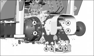
4. Install RSA mounting plates (C) from rear of tractor. Avoid pinching electrical wires.
NOTE: For tractors with hydrostatic transmission, install two additional 5/8 in. hardened washers behind the RSA mounting plates on the forward M16x130 bolt (F).
5. Install two M16x130 bolts (D) and washers, and two M16x140 bolts (E) and washers on both plates. Tighten to 258 N•m (190 lb-ft).
7. Mount rear wheels in widest tread width position. See your machine operator’s manual or technical manual for wheel bolt torque.
Tractor Models 3120-3720
• Use a safe lifting device and support machine securely on jack stands. • Block front and rear of wheel not raised to prevent machine movement. |
1. Raise rear of tractor and support rear axles with jack stands.
NOTE: Rear fenders can be removed to access the top axle flange bolt rather than drilling holes in fenders.
a. Using a 35mm (1-3/8 in.) or larger hole saw, cut a hole (A) through rear fenders in front of ROPS to reach bolt.
b. Remove six bolts (B) from axle flanges on both sides.
4. Install RSA mounting plates (C) from rear of tractor. Avoid pinching electrical wires.
5. Install hardware on both plates:
• Three M14x135 bolts (D) with washers
• Two M14x120 bolts (E) with washers
• One M14x120 bolt (F) with washer and spacer
6. Tighten hardware to 175 N•m (129 lb-ft).
8. Mount rear wheels in widest tread width position. See your machine operator’s manual or technical manual for wheel bolt torque.