
Operating
Daily Operating Checklist
o Test safety systems. Perform safety interlock system checkout procedure.
o Check transmission oil level.
o Check coolant level on liquid cooled engine.
o Remove grass and debris from machine.
o Check area below machine for leaks.
Avoid Damage to Plastic and Painted Surfaces
· Do not wipe plastic parts unless rinsed first.
· Insect repellent spray may damage plastic and painted surfaces. Do not spray insect repellent near machine.
· Be careful not to spill fuel on machine. Fuel may damage surface. Wipe up spilled fuel immediately.
Operator Station Controls
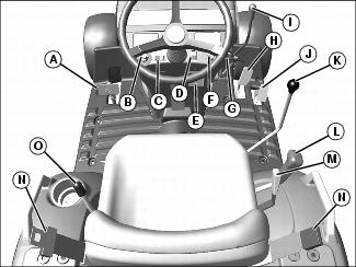
B - Light Control/Warning Flasher Light Switch
F - Power Take Off (PTO) Switch
I - Engine Speed Hand Throttle
K - Selective Control Valve (SCV) Lever
L - Transmission Range Shift Lever
O - Power Take Off (PTO) Selector Lever
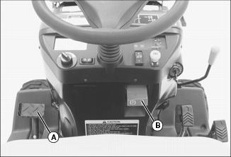
Floor Panel Controls
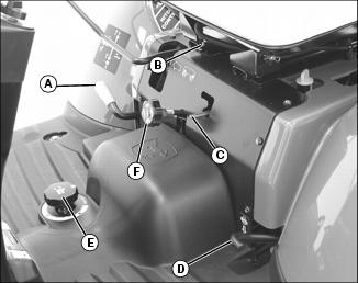
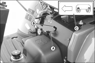
A - Mechanical Front Wheel Drive (MFWD) Control Lever
B - Operator Seat Adjustment Lever
C - Selective Control Valve (SCV) Lock
F - Rockshaft Rate-of-Drop Control Knob
Adjusting Seat
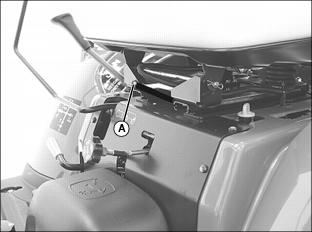
2. Pull seat lever (A) sideways to unlock seat position.
3. Slide seat forward or rearward to desired position where all controls can be easily reached.
4. Release lever to lock seat in position.
Using Seat Belt
Fasten Seat Belt
1. Connect both ends of seat belt.
Adjusting Seat Belt
1. Tighten or loosen seat belt until firmly held onto the seat.
Release Belt
1. Press red button on buckle to release seat belt ends.
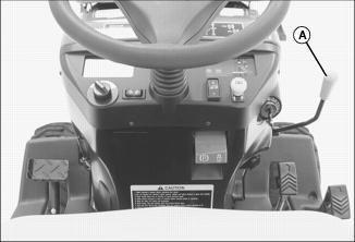
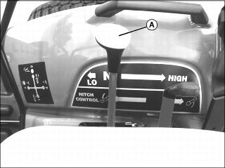
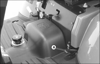
Using Mower Height Control Knob
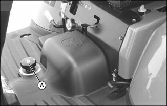
Use mower height control knob (A) to adjust mower cutting height, and lock mower lift kit rear draft arms in raised position. See your mower deck operator's manual for instructions.
Using Light Switch
NOTE: Normal use of turn signals is possible when light switch is in either warning flasher position. Turn signals will temporarily override warning flashers when activated. When turn signals are de-activated, warning flashers will resume operation.
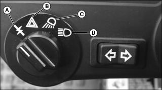
C - Headlights and Taillights On
D - Headlights, Taillights, Warning Flasher Lights On
Using Key Switch
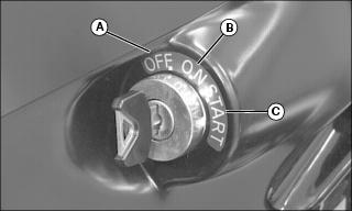
A - OFF Position - In this position the engine will not run.
B - ON Position - Move key from OFF to this position and the engine oil pressure light and battery charging light will turn on and activate the glow plugs for 3 seconds. You will also hear the engine fuel shut-off solenoid engage with a click.
C - START Position - Move key from ON to this position and the starter will engage the engine flywheel to start the engine. Release the key to the ON position.
Using Instrument Panel
Right Side Panel
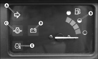
A -Warning Flasher/Turn Signal Indicator Light - This indicator light will turn on and flash when the light switch is turned to the warning flasher lights ON position, the headlights, taillights, and warning flasher lights ON position or the turn signal switch is moved to the right hand turn position.
B - Fuel Gauge - Shows approximately how much fuel is in the fuel tank.
C - Engine Oil Pressure Light - This light will turn on when the ignition key is in the ON position and the engine is not running. If this light turns on while the engine is running, engine oil pressure is too low. Stop engine.
D - Alternator/Battery Charging Light - This light will turn on when the ignition key is in the ON position and the engine is not running. If this light turns on while the engine is running, the alternator output is too low. Move the throttle lever to the full throttle position. Stop the engine if light remains on.
E - Engine Coolant Temperature Light - This light will turn on when the engine coolant is approaching a dangerously hot temperature. If this light turns on during operation, remove load on machine immediately. Reduce engine to idle speed and check for something blocking air flow to the radiator and check engine coolant level. If light stays on after cleaning grille, stop engine.
Left Side Panel
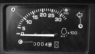
A - Tachometer - Shows engine speed. Engine speed is shown in 100's. Example: If indicator is pointing at 20 (20 x 100 = 2000 RPM). Note the special marker labeled 540. With the indicator pointing at the 540 marker, this is the proper engine speed for the 540 RPM Power Take Off (PTO).
· Slow idle speed........................................1200
· Rated speed.....................................................3000 rpm
· Fast idle speed.........................................3170
B -Warning Flasher/Turn Signal Indicator Light - This indicator light will turn on and flash when the light switch is turned to the warning flasher lights ON position, the headlights, taillights, and warning flasher lights ON position or the turn signal switch is moved to the left hand turn position.
C - Hour Meter - Shows total number of accumulated running hours at rated speed. Use the hour meter as a guide when servicing various components of this machine.
Using Turn Signal Switch
NOTE: The turn signal switch will operate only when the ignition key switch is in the ON position.
NOTE: Normal use of turn signals is possible when light switch is in either warning flasher position. Turn signals will temporarily override warning flashers when activated. When turn signals are de-activated, warning flashers will resume operation.

1. Depress right side of switch (A) to operate the right turn signal light.
2. Depress left side of switch (A) to operate the left turn signal light.
3. Move switch to the centered position to turn lights off.
Testing Safety Systems
The safety systems installed on your machine should be checked before each machine use. Be sure you have read the machine operator manual and are completely familiar with the operation of the machine before performing these safety system checks.
Use the following checkout procedures to check for normal operation of machine.
If there is a malfunction during one of these procedures, do not operate machine. See your authorized dealer for service.
Perform these tests in a clear open area. Keep bystanders away.
Testing the Neutral Start Switch
3. Move the transmission range shift lever to the H (high) or L (low) position.
4. Completely depress the forward or reverse hydrostatic drive pedal.
5. Turn key switch to START position.
Testing the Power-Take-Off (PTO) Switch
2. Move the transmission range shift lever to the N (neutral) position.
4. Turn key to the START position.
Testing the Seat Switch
2. Return hydrostatic travel pedals to neutral position.
5. Move the transmission range shift lever to the H (high) or L (low) position.
6. Raise up slightly from operator's seat. Do not dismount machine.
Using Brake Pedal

1. Depress pedal (A) to operate the brake.
Using Park Brake
NOTE: Label on dash illustrates park brake operation.
Locking Park Brake:
1. Press down completely on brake pedal (A) with foot.
2. Lift park brake lock (B) completely up to the locked position.
3. Remove foot from brake pedal. Pedal should now stay down in the locked position.
Unlocking Park Brake:
1. Press down completely on brake pedal (A) with foot.
2. Push park brake lock (B) completely down to the unlocked position.
3. Remove foot from brake pedal. Pedal should now be released from the locked position.
Using Throttle
Use the throttle to change engine speeds. Use the throttle in conjunction with the tachometer to set engine speeds.
Engine/Tachometer Speeds:
· Slow Idle Speed.......................................1200
· Special Marker 540...........................................2900 rpm
· Rated Speed.................................................... 3000 rpm
· Fast Idle Speed.........................................3170
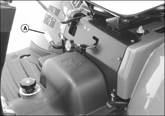
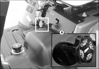
Using Fuel Shut-Off Valve
1. Open or close fuel shut-off valve lever (A) as required:
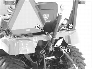
Starting the Engine
1. Open the fuel shut-off valve.
3. Move the 2-speed range lever (A) to the N position.
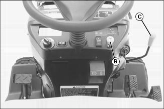
4. Push PTO switch knob (B) down to the disengaged/off position.
5. Lower any implements to the ground.
6. Set hand throttle lever (C) to the 1/2-3/4 fast position.
7. Turn ignition key switch to the ON position.
· Engine oil pressure light will glow.
· Alternator/battery charging light will glow. Engine is now ready to start.
9. Turn key switch to START position. Release key when engine starts.
· Engine oil pressure light should go out within 5 seconds.
NOTE: Set engine speed at full throttle if indicator light does not go out after 10 seconds.
· Alternator/battery charging light should go out within 10 seconds.
· If indicator lights stay on longer than the given time interval, stop engine and check for cause.
IMPORTANT: Avoid damage! In cold weather, run engine several minutes to allow engine oil and transmission oil to warm. |
NOTE: It is normal for the engine to be louder and for blue-white exhaust smoke to be present during engine warm-up. The amount of exhaust smoke depends on air temperature.
11. Set hand throttle lever to the 1/2 fast position for 1 minute without load.
Cold Weather Starting Aids
· Turn key to ON position for 3 seconds to activate glow plugs.
· Install optional engine coolant heater if you operate machine in temperatures below -18° C (0° F).
Warming and Idling the Engine
IMPORTANT: Avoid damage! In cold weather, run engine several minutes to allow engine oil and transmission oil to warm. |
NOTE: It is normal for the engine to be louder and for blue-white exhaust smoke to be present during engine warm-up. The amount of exhaust smoke depends on air temperature.
Warming Engine:
· Set hand throttle lever to the 1/2 fast position for 5 minutes without load.
Idling Engine:
· Adjust hand throttle lever rearward to set engine speed at 1200
Starting a Stalled Engine
IMPORTANT: Avoid damage! If engine stalls while operating under load, start engine immediately to prevent abnormal heat build-up in engine. |
1. Move the 2-speed range lever to the N position.
2. Push PTO switch knob down to the disengaged/off position.
3. Start engine. Continue with normal operation, or set engine speed at slow idle speed for 1 or 2 minutes before stopping.
Stopping Machine
Normal Stopping
1. Remove foot from forward or reverse pedal.
2. Push PTO switch knob down to the disengaged/off position.
3. Lower any implements to the ground.
IMPORTANT: Avoid damage! Do not stop engine immediately after hard or extended operation. Keep engine running at low idle for about 2 minutes to prevent heat build-up. |
6. Adjust hand throttle rearward to set engine speed at slow idle speed. Allow engine to idle for 2 minutes.
7. Turn key switch to OFF position.
9. Wait for the engine and all moving parts to stop before leaving the operator's station.
Emergency Stopping
1. Remove foot from forward or reverse pedal.
3. Turn key switch to OFF position. Do not release brake pedal until all moving parts have stopped.
Operating the Hydrostatic Transmission
NOTE: Label on dash illustrates hydrostatic transmission operation.
IMPORTANT: Avoid damage! To prevent transmission damage, stop machine motion completely before shifting the range shift lever. |
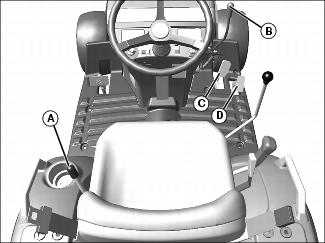
2. Choose speed range with range shift lever (A) to match work application.
6. Move throttle lever (B) forward until engine operates at desired speed.
NOTE: When the travel pedal is released, the transmission will automatically return to neutral.
7. Slowly depress pedal (C) downward to travel forward. Slowly depress pedal (D) downward to travel in reverse.
· The farther either travel pedal is depressed, the faster the machine will travel.
8. Stop machine to change speed range.
Using Optional Cruise Control
NOTE: The cruise control is only operational when the machine is traveling forward.
Engaging Cruise Control
1. Depress forward travel pedal until desired travel speed is reached.
2. Fully depress top of cruise switch (A) to engage cruise control.
3. Release forward travel pedal.
4. To adjust travel speed, disengage cruise control and engage cruise control again at a different speed.
Disengaging Cruise Control
NOTE: The machine will stop if cruise control is disengaged while the machine is in motion. To maintain forward motion, depress the forward travel pedal before disengaging cruise control.
1. Fully depress bottom of cruise switch (A), or depress the right brake pedal.
Using Differential Lock (Traction Assist)
NOTE: Label on dash illustrates differential lock operation.
The differential lock is used to provide better traction when rear wheels start to slip. Engaging differential lock will lock right and left side rear axles together and cause both rear wheels to turn at equal speeds for maximum traction.
NOTE: Turning radius is increased when the differential lock is engaged.
Engaging Differential Lock
1. Stop or slow machine movement.
NOTE: Differential lock will remain engaged as long as rear wheel slippage occurs. If tires slip and regain traction repeatedly, hold down pedal with foot so differential lock remains engaged.
2. Push down on differential lock pedal (A) to engage differential lock.
Disengaging Differential Lock
1. Remove foot from differential lock pedal.
NOTE: Rear wheel slippage will keep differential lock engaged. Lock will automatically disengage when traction equalizes.
2. If lock does not disengage when removing foot from pedal, depress brake pedal to equalize traction, then release.
Using Mechanical Front Wheel Drive (MFWD)
NOTE: Label on dash illustrates MFWD operation.
Mechanical front wheel drive (MFWD) enables the powertrain to drive both front and rear axles for improved traction on difficult ground conditions and provides 4-wheel braking. MFWD can be engaged and disengaged on-the-go with light loads and on low traction surfaces.
NOTE: It may be necessary to reduce engine load to disengage front wheel drive.
Push down on MFWD lever (A) to engage MFWD. Pull up on lever to disengage MFWD.
Tips for Operating MFWD:
· Maintain front tire pressure at maximum allowable level to ensure proper tire performance in all field conditions.
· Engage MFWD to provide four-wheel braking.
· Disengage MFWD when driving machine to or from work site to increase front tire life.
Using the Power-Take-Off (PTO) Safely
Checking PTO Driveshaft Length
IMPORTANT: Avoid damage! The PTO driveshaft is a standard length. Certain driveshaft applications may cause contact with transmission. Driveshaft length may need to be shortened to avoid contact. |
Checking PTO Driveshaft
NOTE: Check PTO driveshaft movement before operating implement.
1. Park machine safely. (See Parking Safely in the Safety section.)
2. Install driveshaft on implement.
3. Install implement on tractor. Do not install driveshaft on tractor.
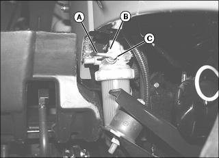
4. Check the fully shortened position of the driveshaft.
a. Push the driveshaft in to its shortest length by hand.
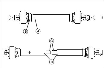
b. Check the area where the outer tube shield (A) meets the shield bell (B).
c. If the outer tube shield does not touch the shield bell, make a mark on the inner tube where the outer tube shield ends.
5. Install driveshaft on tractor and adjust the center link to level the implement for operating while in lowered position. See Using 3-Point Hitch in OPERATING Section.
6. Have an observer stand a safe distance from the implement to tell you when the driveshaft is fully shortened.
7. Set the tractor at low idle and raise the implement, stopping when the observer sees the outer tube shield reach the mark on the inner tube, or the outer tube shield touches the shield bell.
· If the implement is fully raised, and the driveshaft does not reach the fully shortened position, with either the outer tube shield at the mark or touching the bell shield, the driveshaft is ready for operation.
· If the driveshaft reaches the fully shortened position before the implement is fully raised, the driveshaft will need to be shortened.
Shortening the PTO Driveshaft
1. See your John Deere dealer for assistance, or remove 25mm (1 in.) from the ends of the driveshaft (C) and the ends of the shield tubes (D).
2. Check driveshaft length again, and shorten further if needed.
Using Rear and Mid Power-Take-Off (PTO)
IMPORTANT: Avoid damage! Use rear mounted equipment rated for 540 rpm. Do not operate mid or rear PTO over 540 RPM mark on tachometer. |
NOTE: PTO operation for this machine is not intended to be used when the operator is off the seat. The safety interlock system will stop the engine and all implements if the PTO is operating and the operator leaves the seat.
Engaging the PTO
3. Move the 2-speed range lever to the N position.
NOTE: The starter will not crank if the PTO switch knob is in any engaged/on position.
If the operator leaves the seat with the engine running and the PTO engaged, the safety interlock system will stop the engine and all implements.
5. Set engine speed to 1500 rpm or less.
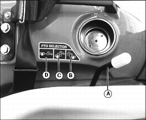
6. Move the PTO control lever (A) to desired operating position.
· Position (B) - Mid PTO only.
· Position (C) - Mid and Rear PTO
· Position (D) - Rear PTO only.
7. Pull PTO switch knob up to the engaged/on position.
8. Adjust the hand throttle lever forward to the desired speed for the implement used.
· Mid PTO speed will be 2100 rpm at the 540 PTO marker on the tachometer.
NOTE: The tachometer indicates a standard 540 PTO at an engine speed of 2900 rpm.
Disengaging the PTO
1. Adjust engine rpm to low idle.
2. Push PTO switch knob down to the disengaged/off position.
Using Rear Hitch
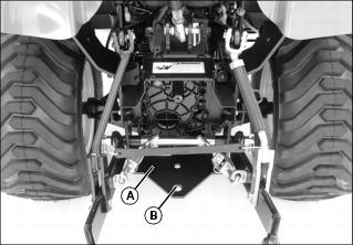
The rear hitch plate (A) provides a single fixed mounting position (B) for towing.
Maximum Hitch Loads
Certain heavy equipment such as a loaded single-axle trailer can place excessive strain on the hitch. Strain is greatly increased by speed and rough ground. Do not exceed 255 kg (562 lb) maximum static vertical load on the rear hitch at position (B).
Using 3-Point Hitch
NOTE: The 3-point hitch on your machine is classified as a limited Category 1 hitch.
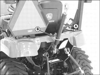
· Place center link (A) in storage hook (B) when hitch is not in use.
Using Rockshaft Control Lever
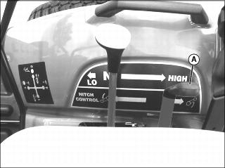
Use rockshaft control lever (A) to raise and lower equipment attached to the 3-point hitch.
Using Rate of Drop/Lock Valve
The rate of drop/lock valve controls the rate of rockshaft drop when the rockshaft control lever is operated. This provides direct rate of drop control for 3-point hitch mounted implements. The valve can also be used to hydraulically lock the rockshaft (three-point hitch) in a desired position.
IMPORTANT: Avoid damage! To prevent overheating hydraulic oil and damaging machine, do not raise rockshaft when drop/lock valve is closed. |
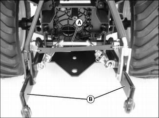
Using the Draft Links
1. Slowly back machine into position to align draft links with implement lift brackets.
2. Park machine safely. (See Parking Safely in the SAFETY section.)
3. Connect draft links (A) to the implement.
4. Secure implement with lynch pins.
Leveling Implement Front-to-Rear
1. Park machine safely. (See Parking Safely in the Safety section.)
NOTE: When the 3-point hitch is not being used, return center link to storage hook (A).
2. Lower implement to ground to relieve pressure on center link.
4. Rotate center link body (C) to lengthen or shorten the center link as needed.
Leveling Implement Side-to-Side
1. Lower any rear mount implement to the ground.
2. Park machine safely. (See Parking Safely in the Safety section.)
4. Rotate lift link body (B) to raise or lower draft link until 3-point hitch mounted implement is level from side-to-side.
Adjusting Implement Side-to-Side Sway
NOTE: Check implement operator's manual procedure for adjusting sway links. When sway links have been properly adjusted, side sway of implement is controlled by position of links.

1. Lower any rear mount implement to the ground.
2. Park machine safely. (See Parking Safely in the SAFETY section.)
4. Rotate turnbuckle (B) to adjust length.
Using Optional iMatch Quick-Attach Hitch System
The optional quick-attach hitch fits all Category I implements designed to the ASAE Cat I standard for quick-attach hitches.
Installing Hitch
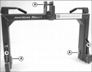
1. Remove three drilled pins (A) and two bushings (B) from quick-attach hitch.
2. Use machine rockshaft control lever to fully lower 3-point hitch draft links.
3. Park machine safely. (See Parking Safely in the SAFETY section.)
4. Position quick-attach hitch near draft links and adjust 3-point hitch sway links to align draft links with quick-attach hitch.
5. Install quick-attach hitch on draft links using drilled pins.
6. Install 3-point hitch center link on quick-attach hitch using center link quick-lock pin and drilled pin.
Connecting Implement
1. Install two bushings included with quick-attach hitch on drilled pins in implement draft link lift brackets.
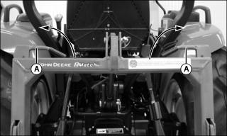
2. Move levers (A) on quick-attach hitch to unlocked position.
3. Back machine into position and align quick-attach hitch with implement lift brackets.
4. Use rockshaft control lever to position quick-attach hitch under lift brackets and lift implement from ground.
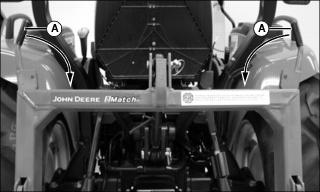
5. Fully raise implement. Move levers (A) on quick-attach hitch to locked position.
Connecting Implement Hydraulic Hoses
1. Park machine safely. (See Parking Safely in the SAFETY section.)
2. Relieve all hydraulic pressure by moving SCV lever rearward-to-forward and side-to-side several times.
3. Refer to implement operator's manual for instructions on connecting hydraulic hoses to couplers.
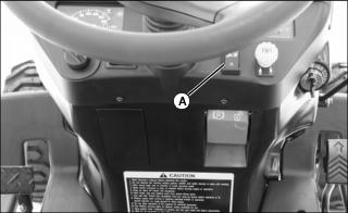
Using Hydraulic Dual Selective Control Valve (SCV)
This machine series is equipped with an hydraulic Selective Control Valve (SCV) and hydraulic outlets to operate hydraulically-driven implements.
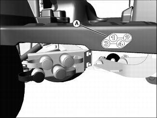
The machine-mounted hydraulic outlets are female quick couplers numbered and color coded for easy hookup. Label (A) identifies the couplers: 1 (yellow), 2 (silver), 3 (black), and 4 (green).
Implement hydraulic hoses are also color coded. Match the color coded hose ends to the color coded hydraulic couplers on the machine when making connections.
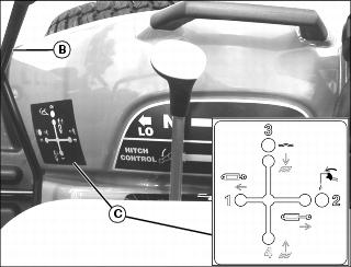
When the implement hydraulic hoses are connected to couplers 1 (yellow) and 2 (silver), move the dual SCV lever (B) left to divert fluid to the yellow connector line and return through the silver connector line. Move the lever right to divert fluid to the silver connector line and return through the yellow connector line. Move the lever to the full right or "regen position" to divert fluid and apply pressure to both connector lines.
When the implement hydraulic hoses are connected to couplers 3 (black) and 4 (green), move the dual SCV lever (B) rearward to divert fluid to the green connector line and return through the black connector line. Move the lever forward to divert fluid to the black connector line and return through the green connector line. Move the lever to the full forward or "float" position to remove pressure in both connector lines and allow fluid to flow back and forth between the lines. The lever may be left in the "float" position.
Refer to information label (C) for assistance. See your implement Operator's Manual for implement functions which correspond to lever positions.
IMPORTANT: Avoid damage! To prevent contamination of female quick couplers, color-coded hose ends should be installed in the couplers when not being used. |
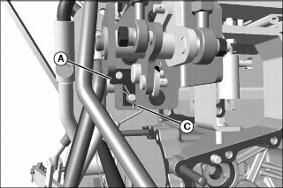
Using Selective Control Valve (SCV) Lock Lever
Picture Note: SCV lock lever shown in the unlocked position.
· Move lock lever (A) to the down position, as shown, to allow SCV lever movement in all directions. Operation of the SCV is unlocked.
· Move lock lever (A) to upper right position (B) to prohibit SCV lever movement in all directions. Operation of the SCV is locked.
· Operation of the lock lever is indicated on label (C).
Locking Out Dual SCV Regen Function
It may be necessary to prevent the dual SCV lever from moving to the full right or "regen" position when operating some implements. See your implement operator's manual.
1. Park machine safely. (See Parking Safely in the SAFETY section.)
2. Remove right rear wheel. (See Removing and Installing Wheels in the SERVICE MISCELLANEOUS section.)
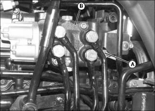
3. Move joystick back and forth to access locking pin on L-shaped bracket (A) on the front of the selective control valve (SCV) (B).
Picture Note: Shown with rear fender platform and closeout panel removed for clarity only.
4. Remove locking pin (C), and L-shaped bracket (A) from pins.
5. Flip L-shaped bracket (A) inverted, and install back onto pins, as shown.
7. Install wheel. Tighten wheel bolts to 88 N·m (65 lb-ft).
Ballasting Machine
IMPORTANT: Avoid damage! Do not overload tires. Do not exceed tire maximum inflation pressure or maximum load capacity. |
Add weight to machine front end if needed for stability. Heavy pulling and heavy rear mounted implements tend to lift front wheels. Add enough ballast to maintain steering control and prevent tip over. Remove weight when it is no longer needed.
Tire Capacities
Use the following charts to determine the tire maximum inflation pressure and load capacity.
Verify maximum tire inflation pressure and maximum load information if embossed into the tire side wall.
* Maximum pressure following tire manufacturer's specifications.
**Maximum load capacity for single tire.
Using Optional Rear Cast Iron Wheel Weights
1. Mount rear wheels in the wide position for improved stability.
2. Fasten weight to each rear wheel using a safe lifting device. A total of three weights per wheel may be used. See your implement operator's manual for installation and number of weights to use.
Rear wheel weights are available from your John Deere Dealer.
Using Optional Rear Ballast Box
The rear ballast box is used for carrying ballast on the 3-point hitch. Approximate weight of different materials is given in the implement operator's manual.
Using Liquid Weight in Tires
NOTE: Use of alcohol as ballast is not recommended. Calcium chloride solution is heavier and more economical.
A solution of water and calcium chloride provides safe economical ballast, and will prevent freezing. If used properly, it will not damage tires, tubes, or rims.
A mixture of 0.4 kg of calcium chloride per liter of water (3.5 lb/gal), will not freeze solid above -45° C (-50° F).
Fill tubeless tires at least to valve stem level (minimum 75% full). Less solution would expose part of rim, possibly causing corrosion.
Tube-type tires may be filled to any level below 90%.
Using Optional Front Weights
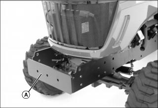
Front weight bracket (A) is an integral part of the machine frame. The bracket will hold up to five Quick-Tatch® weights.
Quick-Tatch weights and attaching hardware are available at your John Deere dealer.
See your implement operator's manual for installation and required number of weights to use.
An optional front weight bracket extension kit is available at your John Deere dealer. This optional front weight bracket extension kit will hold two additional Quick-Tatch weights.
Transporting Machine on Trailer
NOTE: Use a heavy-duty trailer to transport your machine.
1. Drive machine forward onto trailer.
2. Lower any implements to trailer deck.
6. Close the fuel shut-off valve.
7. Fasten machine to trailer with heavy-duty straps, chains, or cables. Both front and rear straps must be directed down and outward from machine. Trailer must have signs and lights as required by law.
Transporting Machine
Driving Machine Safely on Roads
Observe the following precautions when operating the machine on a road:
· Make sure brake linkage is properly adjusted.
· Make sure Slow Moving Vehicle (SMV) emblem and warning lights are clean and visible. If towed or rear-mounted equipment obstructs these safety devices, install SMV emblem and warning lights on equipment.
· Turn on flashing warning lights and headlights, except if prohibited by law.
· Secure towed loads with locked hitch pins and safety chains.
· Drive slowly enough to maintain safe control at all times. Slow down for hillsides, rough ground, and sharp turns, especially when transporting heavy, rear-mounted implements.
· If equipped, disengage the MFWD to reduce tire wear.
· Never coast machine downhill.
Pushing or Towing Machine
1. Push PTO switch knob to the disengaged/off position.
2. Disengage differential lock.
4. Place the range shift lever in the N (neutral) position.
6. Be prepared to use the brake pedal to slow or stop machine.
Towing Loads
1. Hitch the towed load only to the rear hitch plate.
2. Connect safety chains to the lower draft arm crossbar and to the towed load. Provide only enough slack to permit turning.
3. Before descending a hill, shift to a gear low enough to control machine travel speed without having to use the brake pedal to brake the machine and installed implements.
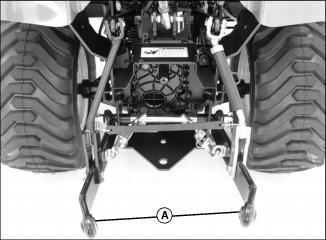
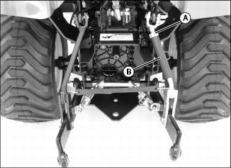
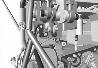
Using Safety Chain
1. Secure the safety chain around the crossbar (A) that supports the lower draft arms (B).