
Service
Service Intervals
Every 10 Hours
• If operating in dry conditions, clean debris from mower.
Every 25 Hours
Every 100 Hours
Every 500 Hours
Grease
The following greases are preferred:
• John Deere Multi-Purpose SD Polyurea Grease
• John Deere Multi-Purpose HD Lithium Complex Grease
If not using any of the preferred greases, be sure to use a general all-purpose grease with an NLGI grade No.2 rating.
Wet or high speed conditions may require use of a special-use grease. Contact your Servicing dealer for information.
Gear Oil
Use oil viscosity based on the expected air temperature range during the period between oil changes.
John Deere GL-5 Gear Lubricant is recommended.
Other oils may be used if they meet one or more of the following:
• API Service Classification GL-5.
• Military Specification MIL-L-2105D.
• Military Specification MIL-L-2105C.
• Military Specification MIL-L-2105B.
Oils meeting Military Specification MIL-L-10324A may be used as arctic oils.
Lubricating Mower
Driveline
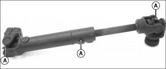
Lubricate grease fittings (A) with recommended grease.
Wheels
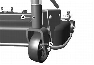
Lubricate grease fittings (A) with recommended grease.
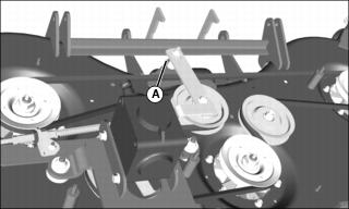
Spindles
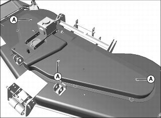
1. Remove plugs in shield to access and lubricate grease fittings (A) with recommended grease.
Idler Arm
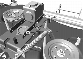
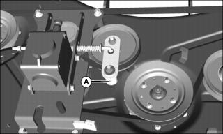
Lubricate grease fitting (A) with recommended grease.
Lubricating Mower Attaching Kit (Large Chassis Tractor)
Lift Arms
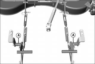
Lubricate grease fittings (A) with recommended grease.
Servicing Gearbox
Checking Oil Level
1. Remove plug from one side of gearbox.
2. Oil level should be even with bottom edge of plug hole.
3. If oil is low, add recommended oil.
Changing Oil
1. Remove gearbox bracket with gearbox. See Removing Belt in SERVICE.
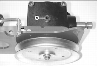
2. Remove plug (A) on both sides of gearbox.
3. Lift and turn gearbox bracket on side to drain oil from gearbox.
4. Route belt around gearbox sheave as you install gearbox bracket on five bolts. See Installing Belt in SERVICE.
5. Following remaining instructions in Installing Belt in SERVICE to install gearbox and rod.
6. Add recommended oil to bottom edge of plug hole in gearbox.
Servicing Mower Belt (72-Inch Models)
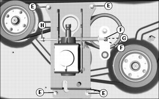
Removing Belt (Large Chassis Mower)
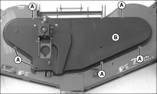
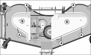
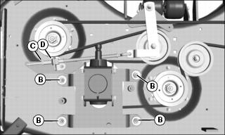
Picture Note: Model with one piece shield is shown. Other models have two piece shield.
2. Remove six locking springs (A) and shield (B).
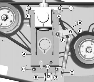
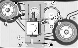
4. Loosen nut (C) to relieve spring tension.
5. Roll the belt off the left sheave.
6. Remove locking pin (D) and washer (E) from end of rod.
7. Remove end of rod from idler arm (F).
9. Remove hanger (H) and belt guide (I).
10. Remove gearbox bracket (J) with gearbox.
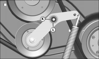
11. Remove nut (K) and washer (L) from idler arm.
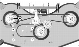
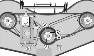
Installing Belt (Large Chassis Mower)
1. Install belt around three sheaves.

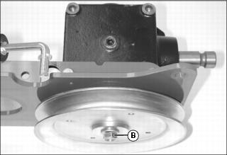
2. Route belt around idler (A) as shown and install idler arm with washer (B) and nut.
3. Remove belt from left sheave.
4. Route belt around gearbox sheave as you install gearbox bracket on five bolts.
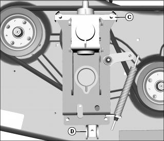
5. Install belt guide (C) and hanger (D).

7. Roll the belt onto left sheave.
8. Install washer (F) and end of rod (G) in idler arm.
10. Adjust nut (I) to leave about 35 mm (1.4 in.) travel distance between nut and bracket.
11. Install shield with six locking rings.
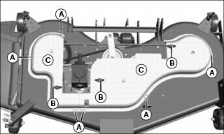
Removing Belt (Mid Chassis Mower)
2. Remove six locking rings (A) and shields (B).
4. Loosen nut (C) to relieve spring tension.
5. Roll the belt off the left sheave (D).
6. Remove locking pin (E) and washers (F) from end of rod.
7. Remove end of rod from idler arm (G).
9. Remove gearbox bracket (I) with gearbox and rod.
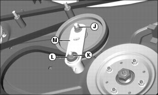
10. Remove locknut (J), locknut (K) and washer (L).
11. Remove idler arm (M) with bushing.
Installing Belt (Mid Chassis Mower)
1. Install belt around three sheaves.
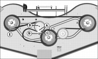
2. Route belt around idler (A) as shown and install idler arm with washer (B), locknut (C) and locknut (D).
3. Remove belt from left sheave (E).
4. Route belt around gearbox sheave as you install gearbox bracket with gearbox on four bolts.
6. Roll the belt onto left sheave.
7. Install washers (F) and end of rod in idler arm.
9. Adjust nut (H) to leave about 35 mm (1.4 in.) travel distance between nut and bracket.
10. Install shields with six locking rings.
Servicing Mower Belt (60-Inch Model)
Removing Belt
2. Remove six locking rings (A), three locking knobs (B) and shields (C).
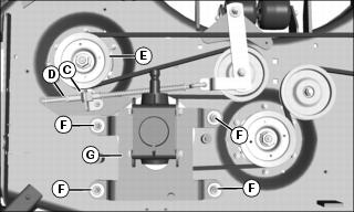
4. Loosen jam nut (C) and turn threaded adjuster bolt (D) to relieve spring tension.
5. Roll the belt off the left sheave (E).
6. Remove four nuts (F) and washers.
7. Remove gearbox bracket (G) with gearbox.
Installing Belt
1. Install belt around three sheaves.
3. Remove belt from left sheave (A).
4. Route belt around gearbox sheave as you install gearbox bracket on four bolts.
5. Install four washers and nuts (B).
6. Roll the belt onto left sheave.
7. Tighten threaded adjuster bolt (C) and jam nut (D). Check belt tension.
8. Install shields with six locking rings and three locking knobs.
Checking and Adjusting Belt Tension
60-Inch Model
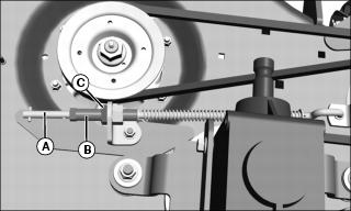
2. Pull sideways on belt and see how much the belt tensioner rod (A) moves within the threaded adjuster bolt (B).
3. If there is more than 10 mm (.4 in.) rod movement, adjust the belt tension.
b. Tighten the adjuster bolt (B) by turning clockwise just enough to compress the spring.
Servicing Mower Blades
Checking for Bent Mower Blades
1. Park machine on a level surface, not on a slope.
7. Wait for engine and all moving parts to stop before you leave the operator’s seat.
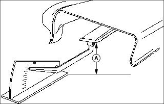
9. Measure the distance (A) from blade tip to level surface with a ruler or a leveling gauge available at your John Deere dealer.
10. Rotate blade 180? and measure the distance between other end of blade and surface.
11. Check all blades. Install new blade if difference between measurements is more than 3 mm (1/8 in.).
Removing Mower Blades
1. Park machine safely. (See Parking Safely in SAFETY.)
3. Use a suitable lifting device to raise mower to gain access to blades.
4. Insert wood block between blade and mower to prevent blade from turning when removing bolt.
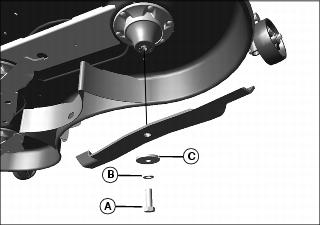
5. Remove bolt (A), washer (B), washer (C) and blade.
Installing Mower Blades
1. Install blade with cutting edge toward the ground.
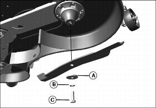
2. Install washer (A), washer (B) and bolt (C).
3. Insert wood block between blade and mower to prevent blade from turning when tightening bolt. Tighten to 122 N•m (90 lb-ft).
Sharpening Blades
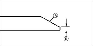
1. Sharpen blade with grinder, hand file or electric blade sharpener.
• Keep original bevel (A) when grinding.
• Blade should have 0.40 mm (1/64 in.) cutting edge (B) or less.
2. Balance blade before installing.
Balancing Blades
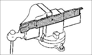
2. Put blade on a nail in a vice or in a vertical wall stud. Turn blade to horizontal position. If blade is not balanced, heavy end of blade will drop.
3. Grind bevel of heavy end. Do not change blade bevel.
Replacing Wheels and Rollers
1. Park machine on a level surface, not on a slope.
7. Wait for engine and all moving parts to stop before you leave the operator’s seat.
Front Wheels
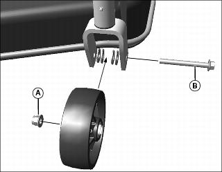
1. Remove nut (A), bolt (B) and four washers as shown.
2. Install new wheel with washers, bolt and nut.
Rear Wheels
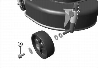
1. Remove bolt (A) and three washers as shown.
2. Install new wheel with washers and bolt.
Rollers
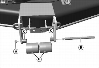
1. Remove nut (A), rollers (B), bushings (C) and shaft
(D) as shown.
2. Install new rollers with bushing, shaft and nut.
Replacing Sheaves
1. Relieve spring tension. See Removing Belt in SERVICE.
2. Roll the belt off one of the sheaves.
• 72-Inch Models: Remove four nuts (A) from each sheave on top of mower.

• 60-Inch Model: Remove nuts (A) from each sheave on top of mower.
Picture Note: 72-inch model shown.