
Assembly
Parts (Large Chassis Tractor Attaching Kit)
NOTE: Some parts are used during mower assembly, others are used during installation on tractor.
Parts (Mid Chassis Tractor Attaching Kit)
NOTE: Some parts are used during mower assembly, others are used during installation on tractor.
Assemble Mower
Install Rear Wheels
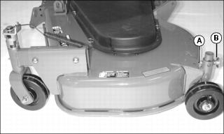
Picture Note: Mower ships from factory with rear wheels installed upside down in wheel shaft supports.
1. Remove locking ring (A) and drilled pin (B) from both rear wheel shafts.
2. Install rear wheels in operating position as shown.
3. Install drilled pins and locking rings.
Install PTO Driveline on Gearbox
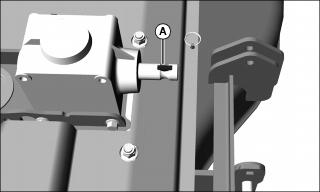
1. Install key (A) in slot in gearbox shaft. Coat shaft with MPG-2 anti-seize lubricant or equivalent.
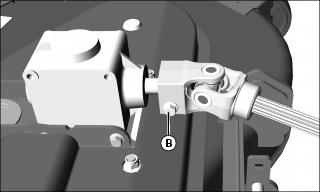
2. Install PTO driveline on gearbox shaft.
3. Install M10x50 bolt (B). Tighten to 75 N•m (55 lb-ft).
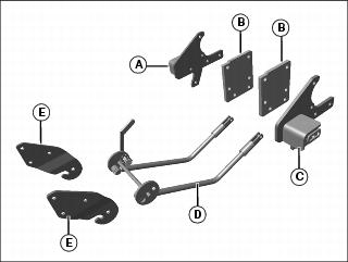
Assemble Mower Attaching Kit (Large Chassis Tractor)
Install Lift Mounting Plates
Picture Note: Installation on machine models 4500-4700 and 4510-4710 requires replacing the lift mounting plates shown. The same hardware is used for installation.
1. Install lift mounting plates (A) to machine frame with six M12x45 bolts (B) and six M12 locknuts.
Install Upper Rear Plates and Rear Draft Deck Supports
1. Remove two bolts (A) and spacers (B) in SCV coupler bracket on right side of machine.
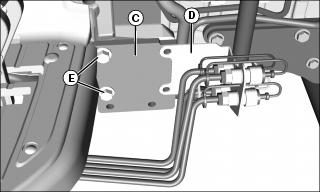
2. Loosely install upper rear plate (C) to machine frame behind SCV coupler bracket (D) with two M16x45 bolts (E).
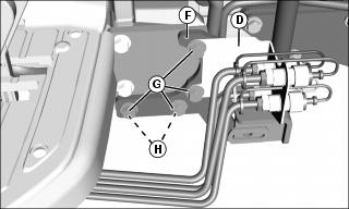
3. Install the SCV coupler bracket (D), right side rear draft deck support (F), and upper rear plate to machine frame with four M16x50 bolts (G) and two M16 nuts (H).
4. Install upper rear plate and rear draft deck support on left side of machine.
5. Tighten all bolts to 275 N•m (210 lb-ft).
Install Upper Plates and Welded Pivot Plates
1. Install right side upper lift plate (A) to ROPS attaching frame with two M12x45 bolts (B) and two M12 locknuts.
2. Models 4500-4700, 4510-4710: Loosen right side ROPS bolt (C) and move spring bracket (D) out of way.
3. Install welded pivot plate (E) to underside of machine axle on right side with two M16x40 bolts (F). Tighten to 285 N•m (210 lb-ft).
4. Move spring bracket (D) back into place. Tighten ROPS bolt (C) to 138 N•m (102 lb-ft).
5. Install left side upper lift plate and welded pivot plate on left side of machine. Do not loosen any left side ROPS bolts.
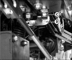
Install Welded Lift Arms
1. Lower machine 3-point hitch to install welded lift arm (A) to raise and lower on 3-point hitch draft links.
2. Install bushing inside tube (B) on welded lift arm.
3. Install welded lift arm between welded pivot plate (C) and upper plate (D) with one square neck bolt, two M17xM34 washers and one M16 nut (E).
4. Repeat installation for welded lift arm on other side of machine.
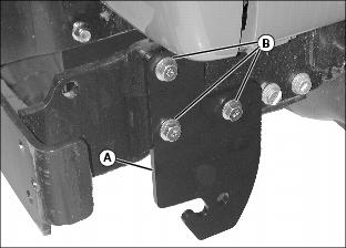
Attach Rear Draft Arms to Mower
1. Loosely install rear draft arm (A) on left rear mower bracket with M12x60 bolt (B), 19 mm (.75 in.) spacer (C), and M12 nut (D).
2. Install rear draft arm and right rear draft arm (E) on right rear mower bracket with M12x90 bolt (F), 19 mm (.75 in.) spacer (G), 27 mm (1 in.) spacer (H), and M12 nut (I).
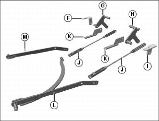
Assemble Mower Attaching Kit (Mid-Chassis Tractor)
NOTE: A mid-mount mower bracket must be installed in place of the MFWD bracket on mid-chassis tractors with cabs before installing mower.
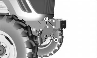
Install Front Attach Brackets
1. Install front attach bracket (A) on both sides of machine frame with three M12x45 bolts (B) and three M12 locknuts.
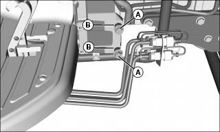
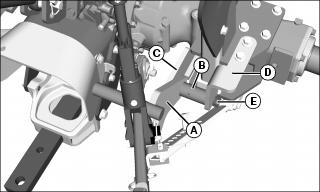
Attach Draft Supports
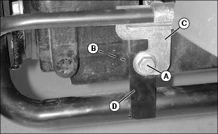
Picture Note: Tractor model shown has hydraulic tube and support bracket (C). Other models may not have tube and support bracket. Follow instructions for parts which are installed.
1. Remove screw (A), spacer (B) in tube support bracket (C), and suction tube strap (D) on left side of machine at front of footdeck. Retain screw.
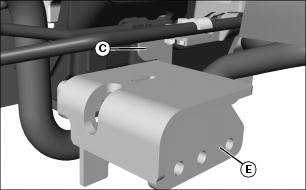
2. Position left draft support (E) behind tube support bracket (C) and suction tube strap (D). Install support with retained screw and one M12x30 screw.
3. Install right draft support (F) on right side of machine frame with M12x30 screw (G) and M12x30 flat head hex screw (H).
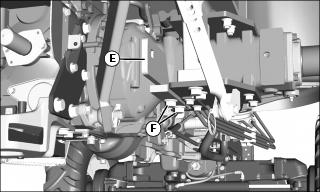
Install Mid-Mount Mower Bracket (Tractor With Cab)
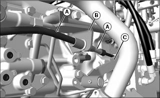
1. Remove tractor MFWD bracket:
a. Locate MFWD cable (A) and bracket (B), at left side of transmission.
b. Remove and retain cotter pin and flat washer securing MFWD cable (A) to shift lever (C) at transmission.
c. Remove and retain locking clip securing MFWD cable in existing MFWD bracket (B), and remove cable from slot in bracket.
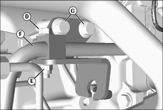
d. Remove and retain the M8x45 capscrew (D) and M8 locknut (E), securing the hydraulic line (F) and clamp to the MFWD bracket.
e. Remove and discard two M10x20 capscrews (G), securing the MFWD bracket to the transmission, then remove and discard the bracket.
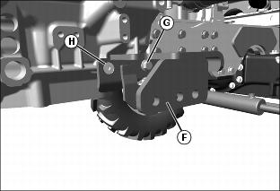
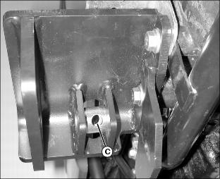
2. Install mid-mount mower bracket:
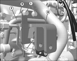
a. Position the mid-mount mower bracket (H), with the upper two mounting holes aligned with the two holes that secured the MFWD bracket to the transmission, and with the hydraulic line (F) and clamp over another mounting hole.
b. Secure the bracket with three M10x25 capscrews (I) , and one M12x25 capscrew (J). Tighten hardware.
c. Secure the hydraulic line and clamp with the M8x45 capscrew (D) and M8 locknut. Tighten hardware.
d. Install MFWD cable into slot in mower bracket and secure with clip.
e. Install cable end into shift lever, and secure with flat washer and cotter pin.
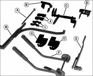
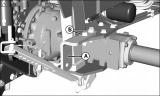
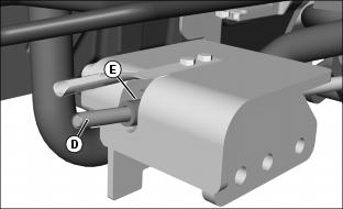
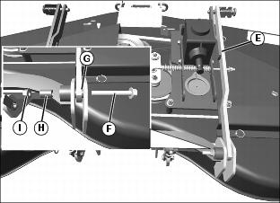
Install Lift Arm Weldment
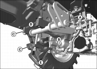
1. Position lift arm weldment (A) under transmission as shown.
2. Install rockshaft bushings (B) in half clamps (C) with flanges toward inside or center of machine.
3. Install lift arm weldment on transmission with two block clamps (D), two rockshaft bushings (B), two half clamps (C) and four M12x90 bolts (E).
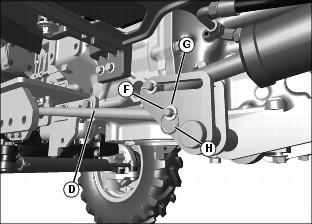
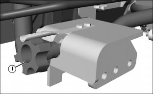
Install Hydraulic Cylinder
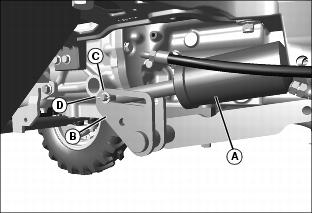
1. Attach rod end of cylinder (A) to lift arm weldment (B) with M12x60 pin, M12 washer (C) and cotter pin (D).
2. Attach head end of cylinder:
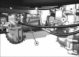
• Tractor without cab: Attach head end of cylinder (A) to bracket (E) on bottom of left hand footdeck support with M12x60 pin (F) and locking ring (G).
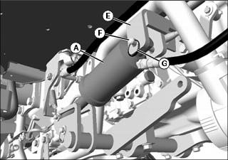
• Tractor with cab: Attach head end of cylinder (A) to bracket (E) with M12x60 pin (F) and locking ring (G).
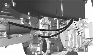
3. Route cylinder hoses up through the opening (H) next to the left side ROPS.
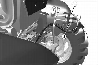
4. Connect cylinder base end hose to top Third SCV outlet (I).
5. Connect cylinder rod end hose to bottom Third SCV outlet (J).
6. Tie hoses to hydraulic line about 15 cm (6 in.) behind bracket (E). Install more ties to secure hoses as needed.
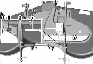
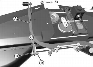
Install Adjustable Depth Rod

1. Install knob retainer (A) on left draft support with two M8x25 bolts (B), two M9 washers and two M8 nuts.
2. Install depth stop (C) on left draft support.
3. Install threaded end of adjustable depth rod (D) through depth stop.
4. Install 14 mm x 25 mm bushing (E) on threaded end of rod.
5. Attach other end of adjustable depth rod (D) to lift arm weldment with M12x60 pin (F), M12 washer (G) and locking ring (H).
NOTE: You may need to adjust the knob (I) to attach adjustable yokes to the mower.
6. Install knob (I) and thread it 4 - 5 turns onto the depth rod.
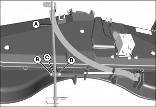
Install Adjustable Yokes
NOTE: Yokes should be preset to 14cm center to center.
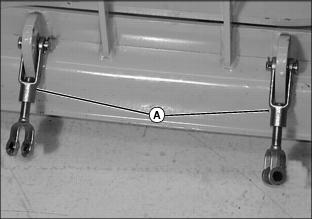
1. Install adjustable yoke assemblies (A) on the lift tabs on the rear of the mower with 12.5 mm x 37 mm pins and cotter pins (B).
Attach Draft Arms to Mower
1. Loosely install draft arm (A) on left rear mower bracket with M12x60 bolt (B), 19 mm spacer (C) and M12 nut (D).
2. Install draft arm and draft arm bar (E) on right rear mower bracket with M12x90 bolt (F), 19 mm spacer (G), 27 mm spacer (H) and M12 nut (I).