
Operating
Raising and Lowering Mower
The mower may be raised or lowered using tractor rockshaft control lever or dual selective control valve (SCV) lever, depending on your installation. Mower lift kits are either mechanical (no hydraulic cylinder) or independent (has hydraulic cylinder).
Mowers With Mechanical Lift Kits
1. Review Using the Rockshaft Control Lever and Using Speed of Drop/Lock Valve instructions in your tractor operator’s manual.
2. Push the rockshaft control lever forward to lower the mower, or pull the lever rearward to raise the mower.
Mowers With Independent Lift Kits
1. Review Using Hydraulic Dual SCV and Using Dual SCV Lock Lever instructions in your tractor operator’s manual.
2. Follow the instructions in your tractor operator’s manual to lock out the dual SCV regen function.
3. Pull the dual SCV lever to the right to lower the mower, or push the lever to the left to raise the mower.
Adjusting Cutting Height
Mower cutting height can be adjusted from approximately 3-15cm (1-6 in.), depending on the tractor. When mower is in highest (transport) position, cutting height is approximately 15cm (6 in.), depending on the tractor.
Cutting height may be adjusted using tractor controls or mower lift kit controls, depending on your installation. Mower lift kits are either mechanical (no hydraulic cylinder) or independent (has hydraulic cylinder).
1. Park machine on a level surface.
6. Set cutting height by method described below for your installation. Mower will be at that cutting height when it is lowered.
2320 Tractor With Any Lift Kit
1. Review Using Mower Height Control Knob instructions in your tractor operator’s manual.
2. Set cutting height with the knob.
2520, 2720 Tractor With Independent Lift Kit
Use the height gauge knob on the lift kit to set cutting height.
4115, 2520, 2720 Tractor With Mechanical Lift Kit
1. Review Using the Rockshaft Control Lever and Using Speed of Drop/Lock Valve instructions in your tractor operator’s manual.
2. Set cutting height with the rockshaft control lever.
Adjusting Mower Wheels
1. Set cutting height. (See Adjusting Cutting Height in OPERATING.)
7. Wait for engine and all moving parts to stop before you leave the operator’s seat.
NOTE: Bottom of wheels should be approximately 6-13mm (1/4-1/2 in.) from the ground.
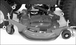
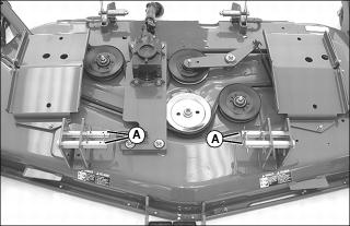
9. Turn quick release pins (A) to open position, move wheels to desired operating position and lock in place with quick release pins.
10. Install pins (B) in lowest shaft hole above wheel bracket to keep same height setting for later mower installations.
12. Lower mower to operating position.
Adjusting Mower Level Front-to-Rear (All Tractor Models)
1. Park machine on a level surface.
NOTE: Mower wheels should not contact the ground during leveling.
3. Lower the mower to desired cutting height.
7. Wait for engine and all moving parts to stop before you leave the operator’s seat.
Checking Blade Height
1. Lift mower discharge chute.
2. Turn the right blade so the tip points straight forward.
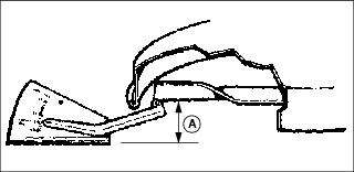
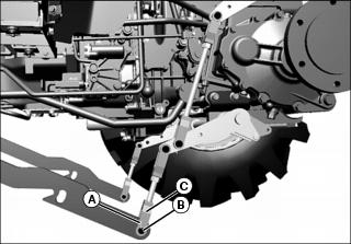
3. Measure the distance (A) from blade tip to level surface, on both ends of the blade, with a ruler or a leveling gauge available at your John Deere dealer.
4. The difference between measurements on both ends of the blade should not be more than 3-6mm (1/8-1/4 in.).
5. If the difference is not within the range, level the mower.
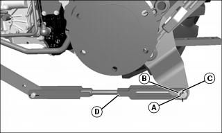
Leveling the Mower

1. Loosen two rear nuts (B) on front hanger.
• Turn two front nuts (C) clockwise to raise front of mower.
• Turn two front nuts (C) counterclockwise to lower front of mower.
3. Measure distance (D) from end of nut to end of bolt. This measurement should be the same on each side of the front hanger.
4. Tighten rear nuts after making adjustment.
5. Measure blade tips again and adjust front hanger if necessary.
Adjusting Mower Level Side-to-Side (2320)
1. Park machine on a level surface.
NOTE: Mower wheels should not contact the ground during leveling.
3. Lower the mower to desired cutting height.
7. Wait for engine and all moving parts to stop before you leave the operator’s seat.
Checking Blade Height
1. Lift mower discharge chute.
2. Turn the right blade sideways.
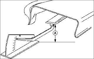
3. Measure the distance (A) from blade edge on outer tip to level surface with a ruler or a leveling gauge available at your John Deere dealer.
4. On other side of mower, turn the left blade sideways. Measure the distance from blade edge on outer tip to level surface.
5. If the difference between measurements on the outer tips of both blades is more than 3mm (1/8 in.), level the mower.
Leveling the Mower

2. Remove spring locking pin (A) and drilled pin (B) from each lift arm.
3. Turn each yoke (C) clockwise to raise the lift arm or counterclockwise to lower the lift arm.
4. Attach each yoke to lift arm with drilled pin and spring locking pin.
Adjusting Mower Level Side-to-Side (4115, 2520, 2720 With Mechanical Lift Kit)
1. Park machine on a level surface.
NOTE: Mower wheels should not contact the ground during leveling.
3. Lower the mower to desired cutting height.
7. Wait for engine and all moving parts to stop before you leave the operator’s seat.
Checking Blade Height
1. Lift mower discharge chute.
2. Turn the right blade sideways.

3. Measure the distance (A) from blade edge on outer tip to level surface with a ruler or a leveling gauge available at your John Deere dealer.
4. On other side of mower, turn the left blade sideways. Measure the distance from blade edge on outer tip to level surface.
5. If the difference between measurements on the outer tips of both blades is more than 3mm (1/8 in.), level the mower.
Leveling the Mower
2. Remove drilled pin (A), washer (B) and cotter pin (C) from each lift arm.
3. Turn rod lift link (D) left (counterclockwise) to lower the mower, or turn rod lift link right (clockwise) to raise the mower.
4. Install lift arms with drilled pins, washers and cotter pins.
5. Start engine and raise mower to cutting height.
Adjusting Mower Level Side-to-Side (2520, 2720 with Independent Lift Kit)
1. Park machine on a level surface.
NOTE: Mower wheels should not contact the ground during leveling.
3. Lower the mower to desired cutting height.
7. Wait for engine and all moving parts to stop before you leave the operator’s seat.
Checking Blade Height
1. Lift mower discharge chute.
2. Turn the right blade sideways.

3. Measure the distance (A) from blade edge on outer tip to level surface with a ruler or a leveling gauge available at your John Deere dealer.
4. On other side of mower, turn the left blade sideways. Measure the distance from blade edge on outer tip to level surface.
5. If the difference between measurements on the outer tips of both blades is more than 3mm (1/8 in.), level the mower.
Leveling the Mower
2. Remove cotter pin (A) and drilled pin (B) from each lift arm.
3. Turn each yoke (C) clockwise to raise the lift arm, or counterclockwise to lower the lift arm.
4. Attach each yoke to lift arm with drilled pin and cotter pin.
Engaging Mower
1. Review instructions on using mid-PTO included in your machine operator’s manual.
2. Follow machine operator’s manual instructions to engage mid-PTO and mower.
Unplugging Mower or Optional Bagger
1. Park machine safely. Wait for all moving parts to stop before getting off to inspect machine.
2. Check under mower deck and discharge chute for debris.
3. Check bagger and bagger chute for debris.
4. Clear all debris before using mower.
Transporting Mower on Machine
Mower can be locked in raised position for transport. Remove mower from transport position before operating.
Transport Position (2320 Tractor)
2. Turn the mower height control knob on the tractor to transport position (highest setting).
Transport Position (2520, 2720 With Independent Lift Kit)
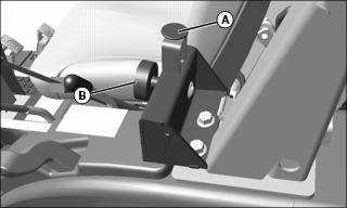
2. Pull the pin (A) in the height gauge assembly and turn the knob (B) completely counterclockwise.
Transport Position (4115, 2520, 2720 With Mechanical Lift Kit)
2. Use the drop/lock valve to lock the rockshaft in fully raised position for transport only.
Transporting Mower on Machine Rear Hitch
Picture Note: Lift pins shown in operating position.
1. Remove spring locking pins and lift pins (A).
Transporting with 3-Point Hitch
1. Review Using 3-Point Hitch instructions in your tractor operator’s manual.
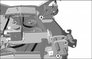
2. Install lift pins (A) as shown.
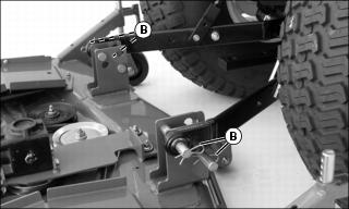
Picture Note: Four spring locking pins (B) are shown. Store other spring locking pins in lift pin holes or off mower.
3. Install draft links on lift pins.
4. Install spring locking pins (B).
5. Raise 3-point hitch high enough for mower to clear the ground.
6. Lock hitch in raised position with drop/lock valve for transport only.
Transporting with iMatchTM Quick Hitch
1. Review Using 3-Point Hitch and Using Optional i-Match Hitch instructions in your tractor operator’s manual.

2. Install lift pins (A) as shown with spring locking pins (B).
3. Install hitch on lift pins.
4. Raise 3-point hitch high enough for mower to clear the ground.
5. Lock hitch in raised position with drop/lock valve for transport only.