
Assembly
Parts
NOTE: Some parts are used during backhoe assembly, others are used during installation on tractor.
Remove Backhoe From Pallet
1. Position pallet on level ground where tractor can be backed up for installation.
2. Remove plastic wrap from seat. Remove seat if not installed.
3. Remove stabilizers or stabilizer legs from pallet.
4. Remove bags covering ends of hydraulic hoses.
5. Remove any bolts and plates securing other parts to pallet. Backhoe may remain on pallet for stability until tractor installation.
6. Backhoe may remain on pallet for stability until tractor installation.
Install Stabilizers
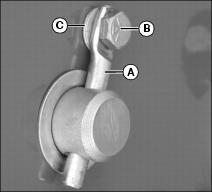
NOTE: Pivot pins on backhoe are installed with either cotter pins or retainers (A). Retainer is installed in pivot pin with bolt (B), 11/32-in. washer (C), and 5/16-in. locknut.
1. Remove pivot pins stored in stabilizers.
2. Remove pivot pins securing cylinders to backhoe, and remove cylinders.
NOTE: Lubricate all pivot pins before installation.
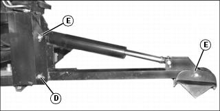
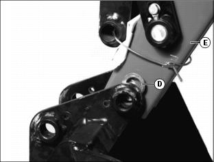
3. Install both stabilizers on backhoe with pivot pin (D) as shown. Install cotter pins or retainers in pivot pins.
4. Install both cylinders on backhoe and stabilizers with pivot pins (E) as shown.
5. Install cotter pins or retainers in pivot pins.
6. Route all hydraulic hoses above the pivot pins.
7. Lubricate all grease fittings and pivot points before operating backhoe.
Install Bucket
NOTE: Lubricate all pivot pins before installation.

NOTE: Pivot pins on backhoe are installed with either cotter pins or retainers (A). Retainer is installed in pivot pin with bolt (B), 11/32 in. washer (C), and 5/16 in. locknut.
1. Grease both sides of two 1-1/32 x 1-1/2 in. washers (D) and install between bucket and dipperstick (E) on both sides of dipperstick.
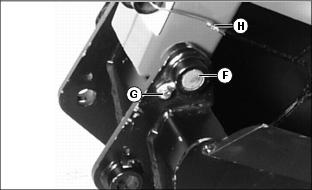
2. Install pivot pin (F) through bucket, washers, and dipperstick.
3. Install two retainers (G) in pivot pin with hardware.
4. Remove shipping wire holding link (H) to dipperstick.
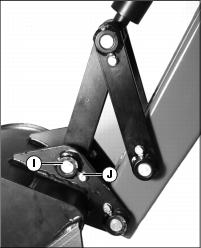
5. Pivot the bucket back and install pivot pin (I) through bucket and link. Install two 1-1/32 x 1-1/2 in. washers between bucket and link if needed.
6. Install two retainers (J) in pivot pin with hardware.
7. Lubricate all grease fittings and pivot points before operating backhoe.
Installing Slow Moving Vehicle (SMV) Sign
NOTE: Use the SMV sign when transporting the backhoe on roads.
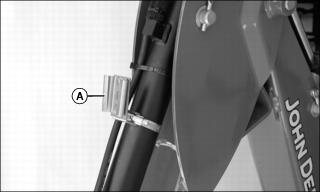
1. Remove SMV sign shipped with backhkoe, and install into bracket (A) on the backhoe bucket cylinder.