
Installing
Install Ballast
When the attachment is removed, also remove any ballast that was added to the machine. Use only attachments and accessories recommended by the manufacturer. |
Front ballast is recommended to counterbalance the rear bagger:
• Install five 19 kg (42 lb) suitcase weights on front of machine.
Installing Bellcrank (2210 and 2305 CUTS)

1. Remove spring locking pin (A) and quick-locking pin (B), and slide spreader bar (C) off of holes in rear lift arms.
2. Remove quick-locking pin (D) and spacer from pivot shaft, and remove the right lift arm (E) and lift link (to prevent it from damaging the MCS frame). Install spacer and quick-locking pin back onto pivot shaft.
NOTE: The bellcrank needs to be installed on left lift arm. This is done to move the lift arm as close as possible to the bellcrank to avoid the MCS frame in the raised position.

3. If bellcrank has not been installed before, remove quick-locking pin (D) and spacer (F) from left lift arm assembly. Retain spacer for future use.
4. Install bellcrank (G) onto pivot shaft (H), aligning hole in bellcrank with hole in left lift arm (I). Install quick-locking pin (D) onto pivot shaft (H).
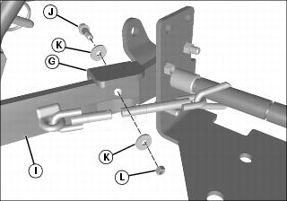
5. Secure left lift arm (I) and bellcrank (G) together with M5x65 shear bolt (J), two M5 washers (K), and an M5 nut (L).

6. Connect lift rod assembly (M) to top hole in bellcrank (G) with one 5/8x1-39/64 in. drilled pin (N), two 11/16 in. washers (O) inside of yoke, and one 3.2x25 mm cotter pin (P).
Installing Lower Mounting Frame
1. Install lower mounting frame on rear of tractor:
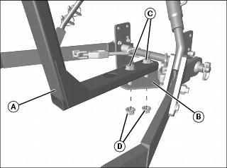
• For 2305 and 2210 tractors, install lower mounting frame (A) onto rear hitch (B) with two M20x60 bolts (C), and M20 flange nuts (D). Tighten hardware to 620 Nm (457 lb-ft).
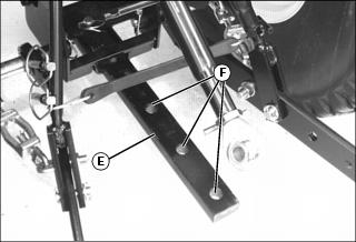
• For 2320, 2520 and 2720 tractors, install rear hitch bar (E) onto rear hitch plate, so three holes (F) on bar are exposed.
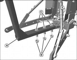
• Install lower mounting frame (A) into rear hitch bar (E) with three M20x60 bolts (C) and M20 flange nuts (D). Tighten hardware to 620 Nm (457 lb-ft).
Installing Center Link
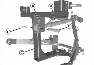
1. Remove pin and locking clip from front of center link (A), and install rear end onto bracket (B) on lower mounting frame (C). Secure with pin (D) and spring locking pin (E).
2. Rotate center link (A), as necessary, and secure front of center link back onto machine. Rotate center link (shortening length) until tight.
Installing Hopper Assembly
1. Park the machine safely. (See Parking Safely in the SAFETY section.)
2. Remove bags from bagger assembly.
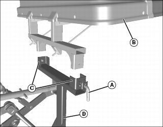
3. Pull outward, and move upper CLICK-N-GO™ pins (A) on both sides to the locked open position (vertical).
4. Lower hopper assembly (B) onto slotted brackets (C) on lower mounting frame (D).
NOTE: It may be necessary to shift the bagger assembly slightly to ensure the CLICK-N-GO pins (A) have locked securely into the mounting holes of the bagger latches when installing.
5. Release the upper CLICK-N-GO pins (A) from the locked open position (to the horizontal position) so they lock into the mounting holes in the slotted brackets (C).
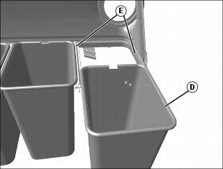
6. Slide bags (D) into position on support frame (E) so the safety decals are visible at rear of machine.
Adjusting Hopper
NOTE: Machine must be parked on a level surface with tires inflated to the correct air pressure before adjusting the hopper.
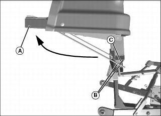
Picture Note: Shown without bags to show nut locations.
2. Stand to the side of the hopper. Support frame (A) should be angled 2-3? forward of level. Adjust hopper if necessary:
a. Loosen M10 flange nuts (B) on both hopper support rods.
b. Adjust nuts evenly on both sides until support frame is angled slightly forward.
c. Tighten nuts onto upper mounting frame brackets (C).
Installing Power Flow Chute

1. Cut end of chute, and drill a 5 mm (3/16 in.) hole (chute latch hole indention is molded into plastic) in the center of chute according to the chart above.
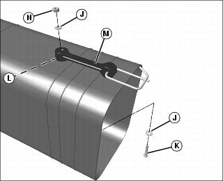
2. Install 7/32 in. washer (J) on 3/16 x 1-1/4 in. machine screw (K). Put screw through chute latch hole (L) from inside of chute - hole determined by chart above.
3. Fasten strap (M) to chute with second 7/32 in. washer (J) and 3/16 in. locknut (N).
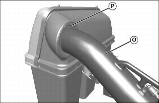
4. Insert round end of chute (O) into hopper opening (P). Guide chute into hopper far enough to provide clearance for connection to the POWER FLOW.
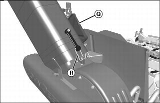
5. Lift and hold open exhaust door (Q) on the POWER FLOW.
6. Slide chute completely onto blower outlet.