Service Electrical
Battery Statement
Service the Battery Safely

Checking Battery Electrolyte Level
NOTE: Add only distilled water to replace battery electrolyte.
1. Park the machine safely. (See Parking Safely in the SAFETY section.)
2. Remove battery cell caps. Make sure cap vents are not plugged.
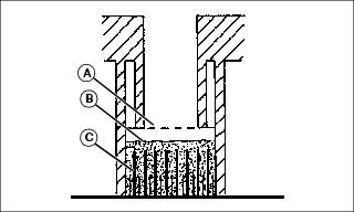
3. Check electrolyte level. Electrolyte (B) should be approximately halfway between bottom of filler neck (A) and top of plates (C).
IMPORTANT: Avoid damage! Do not overfill battery. Electrolyte can overflow when battery is charged and cause damage. |
4. Add only distilled water if necessary.
Removing and Installing Battery
Removing:
1. Park machine safely. (See Parking Safely in the Safety Section.)
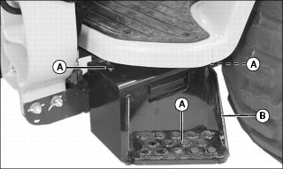
2. Remove three spring locking pins (A) and battery box step plate (B).
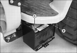
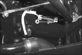
3. Disconnect negative (-) battery cable (C).
4. Push red cover back away from positive (+) battery cable (D) and remove cable from battery.
Installing:
1. Install battery into battery box.
2. Connect positive (+) cable to battery first, then negative (-) cable.
3. Apply dielectric grease to terminals to prevent corrosion.
4. Slide red cover over positive battery cable.
6. Install spring locking pins (B).
Cleaning Battery and Terminals
1. Park machine safely. (See Parking Safely in the SAFETY section.)
2. Disconnect and remove battery.
3. Wash battery with solution of four tablespoons of baking soda to one gallon of water. Be careful not to get the soda solution into the cells.
4. Rinse the battery with plain water and dry.
5. Clean terminals and battery cable ends with wire brush until bright.
7. Attach cables to battery posts using washers and nuts.
8. Apply spray lubricant to terminal to prevent corrosion.
Using Booster Battery
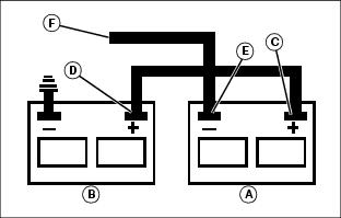
1. Connect positive (+) booster cable to booster battery (A) positive (+) post (C).
2. Connect the other end of positive (+) booster cable to the disabled vehicle battery (B) positive (+) post (D).
3. Connect negative (-) booster cable to booster battery negative (-) post (E).
4. Connect the other end (F) of negative (-) booster cable to a metal part of the disabled machine engine block away from battery.
5. Start the engine of the disabled machine and run machine for several minutes.
6. Carefully disconnect the booster cables in the exact reverse order: negative cable first and then the positive cable.
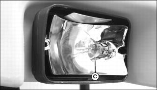
Replacing Canopy Work Light Assemblies
1. Park machine safely. (See Parking Safely in the SAFETY section.)
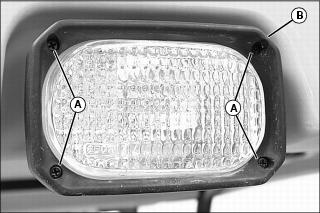
2. Remove screws (A) and bezel (B).
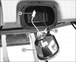
3. Carefully remove light assembly (C) from light housing.
4. Disconnect wire connectors (D).
5. Install new work light assembly.
7. Install bezel (B) and screws (A).
Replacing Canopy Warning Light Bulbs
Replace Front Warning Light Bulbs
1. Park machine safely. (See Parking Safely in the SAFETY section.)
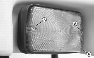
2. Remove screws (A) and lens (B).
3. Push down and rotate bulb (C) to remove.
4. Push new bulb into socket and rotate to lock in place.
6. Install lens (B) and screws (A).
Replace Rear Warning Light Bulbs
NOTE: Each warning light assembly facing to the rear is divided into two sections. The top lens sections are amber and used for turn signals and warning flashers. The bottom lens sections are red and used for brake lights and taillights.
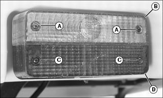
1. Remove screws (A) and lens (B) if bulb replacement is required behind the amber lens section.
2. Remove screws (C) and lens (D) if bulb replacement is required behind the red lens section.
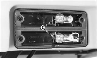
3. Push down and rotate bulb (E) to remove.
4. Push new bulb into socket and rotate to lock in place.
Replacing Instrument Panel Light Bulbs
1. Park machine safely. (See Parking Safely in the SAFETY section.)
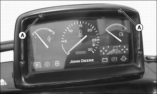
2. Remove four screws (A) from instrument panel housing. Carefully move housing to the left.
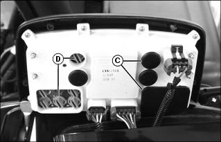
3. Identify defective bulb location.
4. Remove rubber plug(s) (C) to locate indicator light bulb assemblies.
5. Rotate bulb assembly (D) counterclockwise and remove from the housing socket.
6. Install new bulb assembly with same type bulb into housing socket and rotate clockwise into a locked position.
9. Install instrument panel housing and screws.
Replacing Fuses
IMPORTANT: Avoid damage! The electrical system may be damaged if incorrect replacement fuses are used. Replace the bad fuse with a fuse of the same amp rating. |
1. Park machine safely. (See Parking Safely in the SAFETY section.)
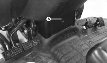
2. Raise lever (A) and lower fuse block access door.
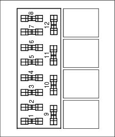
4. Pull defective fuse from socket.
6. Close fuse block access door.
NOTE: Do not install a fuse into fuse position twelve shown above. Installing a fuse into this position will disable the transmission.