
Service
Lifting Tiller
Some models have a bracket located near the gearbox for lifting. Other models have a clevis attached to the gearbox for lifting.
Service Intervals
IMPORTANT: Avoid damage! If tiller is operated in extreme heat, dust, or other severe conditions, service functions may need to be performed more often than shown below. |
Every 8 Hours
• Grease PTO driveline U-joints.
• Grease PTO driveline shield.
Every 50 Hours
• Tighten all screws and bolts.
Every 500 Hours
• Models 665, 673: Check chain deflection and adjust chain tension as necessary.
Grease
The following greases are preferred:
• John Deere Multi-Purpose SD Polyurea Grease
• John Deere Multi-Purpose HD Lithium Complex Grease
If not using any of the preferred greases, be sure to use a general all-purpose grease with an NLGI grade No.2 rating.
Wet or high speed conditions may require use of a special-use grease. Contact your Servicing dealer for information.
Lubricating
PTO Driveline
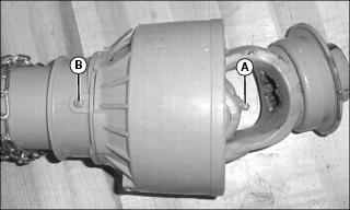
• Lubricate grease fitting (A) on U-joints at both ends.
• Lubricate shield grease fitting (B) at both ends.
• Separate driveline and apply grease to inner shaft.
Rotor Bearing (647, 665, 673)
1. Lubricate grease fitting (A).
Rotor Bearing (655)
3. Grease inner rotor bearing.
4. Replace cover in original position.
Rotor Bearing (681)
2. Roll tiller forward to drain oil. Return tiller to upright position.
3. Install and tighten check plug to 25 N•m (17.5 lb-ft).
5. Add gear oil until oil begins to drain from plug hole.
6. Install and tighten fill plug to 25 N•m (17.5 lb-ft).
Gear Case Oil
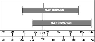
Use oil viscosity based on the expected air temperature range during the period between oil changes
The following John Deere gear case oil is preferred:
• GL-5 GEAR LUBRICANT® (SAE 80W-90)
The following John Deere gear case oil is also recommended if preferred oil is not available:
• GL-5 GEAR LUBRICANT® (SAE 85W-140)
Other gear case oils may be used if recommended John Deere gear case oils are not available, provided they meet the following specification:
• API Service Classification GL–5.
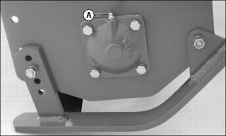
Checking and Changing Gearbox Oil
IMPORTANT: Avoid damage! Clean area around plugs before removing to prevent dirt and other contaminants from entering oil reservoir. |
NOTE: Be sure top of tiller is level before checking and changing oil.
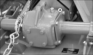
a. Remove check plug (A) on top of gear box. Add gear oil until visible on the dipstick.
b. Install and tighten check plug to 25 N•m (17.5 lb-ft).
a. Remove tiller from machine.
b. Locate and remove drain plug from bottom of gearbox. On some models, remove the guard and the PTO driveline from the tiller to access the drain plug.
d. Install and tighten drain plug to 25 N•m (17.5 lb-ft). Install PTO driveline and guard if removed.
e. Remove check plug (A) on top of gear box.
f. Add gear oil until visible on the dipstick.
g. Install and tighten check plug to 25 N•m (17.5 lb-ft).
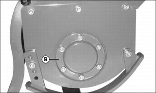
Checking and Changing Chaincase Oil
IMPORTANT: Avoid damage! Clean area around plugs before removing to prevent dirt and other contaminants from entering oil reservoir. |
NOTE: Be sure top of tiller is level before checking and changing oil.
NOTE: Be sure top of tiller is level before checking and changing oil.
NOTE: On some models, check plug does not have glass display. Remove check plug to check oil level, and add oil until oil comes out check plug hole.
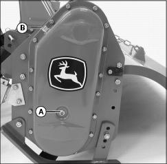
a. Locate check plug (A) on chaincase. Oil should be seen in check plug.
c. Add gear oil until seen in check plug.
d. If removed, install and tighten check plug to 25 N•m (17.5 lb-ft).
e. Install and tighten fill plug to 25 N•m (17.5 lb-ft).
NOTE: Gasket must be replaced when chaincase cover is removed.
b. Loosen chaincase cover bolts to drain oil.
c. Remove cover and replace gasket.
d. Install cover and tighten bolts.
e. Add gear oil until seen in check plug.
f. If removed, install and tighten check plug to 25 N•m (17.5 lb-ft).
g. Install and tighten fill plug to 25 N•m (17.5 lb-ft).
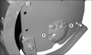
Replacing Tines
1. Block tiller in raised position.
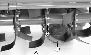
2. Stand facing tiller rear to identify tines:
• Left-hand tine (A) curves to the left when the cutting edge is forward.
• Right-hand tine (B) curves to the right when the cutting edge is forward.
NOTE: When replacing tines, note tine and hardware positions before removal. Remove one tine and install replacement before proceeding to the next tine. This will ensure the pattern and hardware configuration is maintained.
3. Remove nuts (C), lockwashers and bolts.
4. Install replacement tine with cutting edge forward.
5. Install bolts, lockwashers and nuts. Tighten to 95 N•m (70 lb-ft). On model 647 only, tighten to 129 N•m (95 lb-ft).
Adjusting Drive Chain Tension
NOTE: Models 647 and 655 have an automatic spring tensioner and require no adjustment.
Model 665, 673
These models may require adjustment depending on the amount of chain deflection.
1. Remove the chaincase cover.
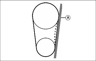
2. Align a straight edge (A) between the gears.
3. Push the chain mid point between the gears to check deflection.
4. If deflection exceeds 0.25 in. (5mm) adjust the tensioner:
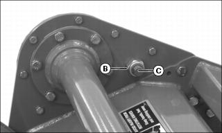
a. Loosen jam nut (B) enough to turn in screw (C) and increase tension.