
Assembly
Bag of Parts (647)
NOTE: Hardware is grouped with part. Match hardware with parts before starting assembly. Hardware listed with park stand is installed at factory.
Front Park Stand
Rear Park Stand
Mast
PTO Guard
Draft Link Brackets
Leveling Chain
Bag of Parts (655)
NOTE: Hardware is grouped with part. Match hardware with parts before starting assembly. Hardware listed with park stand is installed at factory.
Front Park Stand
Rear Park Stand
Mast
PTO Guard
Draft Link Brackets
Leveling Chain
Bag of Parts (665, 673)
NOTE: Hardware is grouped with part. Match hardware with parts before starting assembly. Hardware listed with park stand is installed at factory.
Front Park Stand
Rear Park Stand
Mast
PTO Guard
Draft Link Brackets
Leveling Chain
Bag of Parts (681)
NOTE: Hardware is grouped with part. Match hardware with parts before starting assembly. Hardware listed with park stand is installed at factory.
Front Park Stand
Rear Park Stand
Mast
PTO Guard
Draft Link Brackets
Leveling Chain
Install Parts
Install Mast
NOTE: Brackets for mast installation have upper and lower rows of 4 holes. Install mast in lower row of holes.
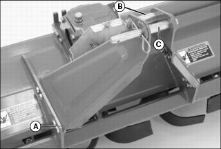
Picture Note: Some models have a one part mast or different style hitch pin.
1. Install left and right mast sides, or one-part mast, with 8 bolts (A) and nuts. Tighten to specification in following chart.
2. On models with two-part masts, install bolt, spacer (B) and nut in rear hole in top of mast. On models with two rear holes, install two bolts and hardware.
3. On models with two-part masts, install hitch pin (C) and cotter pin in front hole. Install iMatch upper bushing on hitch pin if optional quick-attach hitch is used.
Install PTO (Power-Take-Off) Driveline
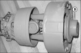
• Connect driveline with collar (D):
a. Pull collar back and install driveshaft on machine PTO shaft.
b. Release collar. Push and pull driveshaft to be sure collar is locked.
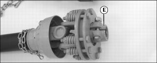
• Connect driveline with clamp (E):
a. Install driveshaft on tiller PTO shaft.
Install PTO Driveline Guard
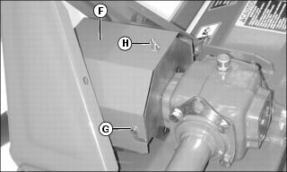
1. Install guard (F) on pins (G).
2. Install washer and wing nut (H).
Install Draft Link Brackets
NOTE: Some models have left and right brackets. On these models, each bracket has two holes with different diameters. Install these brackets with the smaller holes closest to the PTO driveshaft.
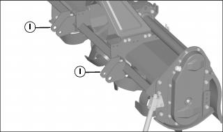
1. Loosely install brackets (I) over decals on front bar with U-bolts and nuts.
2. Measure distance between centers of brackets. Position brackets 681-684mm (26.8 - 26.9 in.) apart, centered with the mast.
3. On models with a one part mast, install the third bracket in the center on top of mast.
4. Tighten nuts to secure brackets.
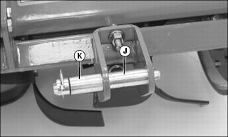
Picture Note: Some models have different style hitch pin. Model 647 shown.
5. Install hitch pin (J) and cotter pin in brackets.
• Install iMatch lower bushings on hitch pins if optional quick-attach hitch is used.
• On Model 647, install spacers (K).
Install Front and Rear Park Stands
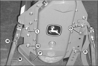
1. Install front park stand bracket (L) on left side of tiller using hardware installed in that position at the factory.
2. Install park stand (M) in lowest position with adjustment pin (N) and locking hairpin. Some models have an adjustment pin which uses a quick lock pin.
3. Install rear park stand bracket with two bolts (O) and nuts. For some models with preassembled parking stands, install one bolt and nut.
4. Install park stand in bracket with bottom surface parallel to ground, and install spring pin in top hole of park stand.
5. Move park stand to lowest position, and install adjustment pin with locking hairpin or quick lock pin.
6. If skid shoes (P) are not in lowest position:
a. Loosen nut (Q) on pivot bolt.
b. Remove nut (R), lockwasher and bolt.
c. Adjust both skid shoes to lowest position. Install bolts, lockwashers and nuts. Tighten all nuts.
7. Lower the tiller to support the weight on the park stands and right side skid shoe.
Install Leveling Board Chain
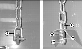
1. Use hardware supplied with your model to install chain on leveling board as shown:
• Hook (T) with spring (U), washer (V) and nut (W).
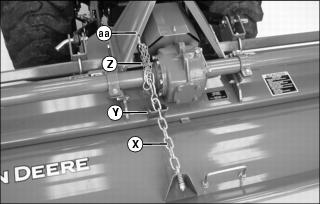
Picture Note: Some models have two leveling board chains.
2. Raise leveling board off the ground and install chain (X) in bracket (Y).
3. Install small chain (Z) in leveling board chain link and in hole (aa) in mast to secure leveling board chain.