
Installing
Preparing Machine
Required Equipment
Compact utility tractor must have a Category 1, 3-point hitch installed before installing the tiller.
Installing Ballast
Machines With Category 1, 3-point Hitch Only
*A weight extension bracket must be used to install the required weights on this machine model or series.
**The number of 32 kg. (70 lb) front weights. Numbers in brackets [ ] are 20 kg. (42 lb) front weights to be used.
Machines With Optional iMatch™ Quick-Attach Hitch
*A weight extension bracket must be used to install the required weights on this machine model or series.
**The number of 32 kg. (70 lb) front weights. Numbers in brackets [ ] are 20 kg. (42 lb) front weights to be used.
All Other Machines
Contact your John Deere dealer to confirm the tiller is compatible with your tractor model.
Find the Implement Code for your tiller model in the following table, and see the Ballasting Machine instructions in your tractor operator’s manual to find the number of weights required. If installing the tiller on the Autohitch, use the Autohitch Code from the following table, and see the Implement Code Using iMatch Quick-Attach Hitch table in your tractor operator’s manual.
Installing Tiller
IMPORTANT: Avoid damage! Gearbox and chaincase are shipped with oil. Check oil levels before operating tiller. |
1. Review instructions on using 3-point hitch, using optional iMatch™ (quick-attach) hitch, and using rear PTO included in your machine operator’s manual.
2. Follow machine operator’s manual instructions to position 3-point hitch center link in middle hole of mounting bracket for medium and heavy draft load.
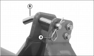
Picture Note: Some models have different style hitch pin. Bushings are also installed on hitch pins when optional quick-attach hitch is used.
3. Remove three cotter pins (A) and hitch pins (B) stored in tiller center link bracket and draft link brackets.
4. Follow machine operator’s manual instructions to:
a. Adjust 3-point hitch draft links to rigid position.
b. Install optional quick-attach hitch.
c. Install tiller on quick-attach hitch or on machine 3-point hitch draft links and center link using hitch pins and cotter pins. Install iMatch bushings on hitch pins if optional quick-attach hitch is used.
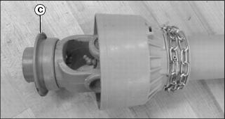
5. Install tiller PTO driveshaft on machine:
a. Pull collar (C) back and install driveshaft on machine PTO shaft.
b. Push driveshaft until it snaps into locked position. Push and pull driveshaft to be sure collar is locked.
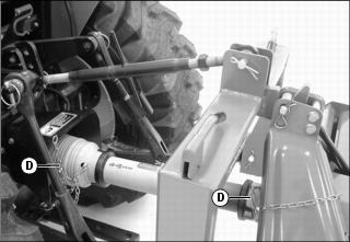
Picture Note: Optional quick-attach hitch shown.
c. Connect driveshaft guard chains (D) to tiller mast and machine PTO guard. Allow guard to turn freely.
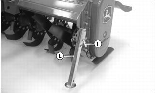
6. Follow machine operator’s manual instructions to use the rockshaft control lever and raise the tiller off the park stand (E).
7. Remove locking pin (F) and fully raise the front park stand.
8. Install locking pin and cotter pin as shown. Some models have a locking pin which does not use a cotter pin.
9. Raise and lock the rear park stand (not shown).
10. Follow machine operator’s manual instructions to:
a. Level tiller front-to-rear and side-to-side.
b. Adjust tiller side-to-side sway to a maximum of 25 mm (1 in.) on each side.