
Service Engine
Engine Warranty Maintenance Statement
Maintenance, repair, or replacement of the emission control devices and systems on this engine, which are being done at the customer’s expense, may be performed by any non-road engine repair establishment or individual. Warranty repairs must be performed by an authorized John Deere dealer.
Avoid Fumes
Engine Oil - Diesel
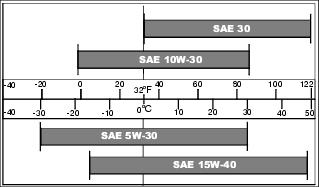
Use oil viscosity based on the expected air temperature range during the period between oil changes.
The following John Deere oils are preferred:
Other oils may be used if above John Deere oils are not available, provided they meet the following specification:
• API Service Classification CH or higher
• ACEA Specification E3 or higher
Checking Engine Speeds
Check engine speeds when engine is warmed up and not under load.
• Fast idle (no load) - 2920 rpm
• Slow idle (no load) - 925 rpm
If above engine speeds are not to specifications, see your John Deere dealer.
Checking Engine Oil Level
NOTE: Check oil twice a day if you run engine over 4 hours in a day.
Make sure engine is cold when checking engine oil level.
1. Park the machine safely. (See Parking Safely in the SAFETY section.)
IMPORTANT: Avoid damage! Dirt and contamination can enter engine when checking oil level. Clean area around dipstick before loosening or removing. |
5. Remove dipstick (A). Wipe it clean with a rag.
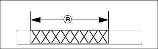
7. Remove dipstick. Verify oil on dipstick is within operating range (B).
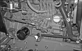
a. Remove right side panel and remove oil fill cap (C).
b. Add proper engine oil until level is within operating range on dipstick. Do not overfill.
10. Install and tighten oil fill cap.
Changing Engine Oil and Filter
IMPORTANT: Avoid damage! Change the oil more often if the vehicle is used in extreme conditions: |
1. Run engine to warm the oil.
2. Park machine safely. (See Parking Safely in the SAFETY section.)
4. Put drain pan under oil drain located under engine.
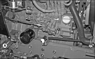
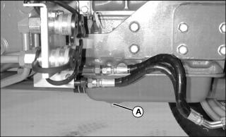
5. Loosen and remove oil drain plug (A). Allow all engine oil to drain.
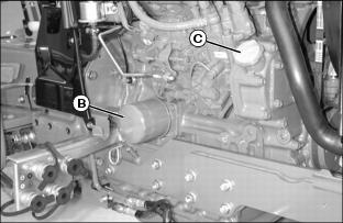
7. Wipe dirt from around oil filter (B).
8. Turn filter counterclockwise to remove.
9. Apply a film of clean engine oil on gasket of new filter.
10. Install filter. Turn filter clockwise until gasket makes contact with filter base. Tighten additional one-half turn.
11. Install drain plug. Do not overtighten.
13. Add 5.3 L (5.6 qt) of oil into fill opening.
14. Install and tighten oil fill cap.
15. Start and run engine at idle to check for leaks.
16. Stop engine. Fix any leaks before operating.
17. Check engine oil level, add oil if necessary.
Cleaning Dust Unloading Valve
IMPORTANT: Avoid damage! Do not operate engine without air cleaner element and rubber dust unloading valve installed. |
1. Park the vehicle safely. (See Parking Safely in the SAFETY section.)
3. Access the engine compartment.
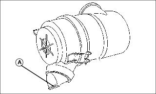
4. Squeeze dust unloading valve (A) to clean. Remove and replace if damaged.
Checking Optional Air Restriction Indicator
1. Park machine safely. (See Parking Safely in the SAFETY section.)
NOTE: Indicator will not function correctly if plastic indicator housing is damaged.
3. Locate and check air restriction indicator (A).
• If red plunger inside indicator is visible, the air filter elements require immediate service.
4. Service air cleaner elements if needed.
Servicing Air Cleaner Elements
Primary Air Filter Element
1. Park the machine safely. (See Parking Safely in the SAFETY section.)
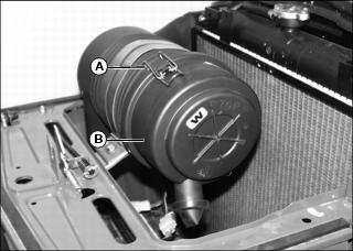
3. Release latches (A) and remove air cleaner canister cover (B).
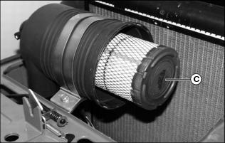
4. Remove and discard primary element (C). Replace with a new primary element.
5. Install air cleaner canister cover (B) with rubber dust unloading valve pointing downward.
6. Hook latches (A) onto cover.
7. If installed, push reset button on top of air restriction indicator.
8. Start engine. Allow engine to run approximately one minute at high idle.
10. Check air restriction indicator. If red plunger inside is visible, replace secondary air filter element.
Secondary Air Filter Element
1. Remove air cleaner canister cover.
2. Remove primary air filter element.
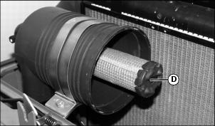
3. Remove and discard secondary air filter element (D). Replace with a new secondary air filter element.
4. Install primary air filter element.
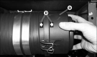
5. Install cover (B) onto air filter canister so arrows (D) are aligned. Secure latches.
6. If installed, push reset button on top of air restriction indicator.
7. Start engine. Allow engine to run approximately one minute at high idle.
9. Check air restriction indicator. If red plunger inside is visible, replace secondary air filter element.
Checking Air Filter Intake Hoses and Clamps
1. Park machine safely. (See Parking Safely in the SAFETY section.)
Service Cooling System Safely
Recommended Engine Coolant
The following John Deere coolants are preferred:
• COOL-GARD II® PRE-DILUTED SUMMER COOLANT (TY26576).
• COOL-GARD II® CONCENTRATED SUMMER COOLANT (TY26573).
If neither of the recommended coolants is available, use a glycol base coolant that meets the following specification:
Check container label before using to be sure it has the appropriate specifications for your machine. Use coolant with conditioner or add conditioner to coolant before using.
If using concentrate, mix approximately 50 percent antifreeze with 50 percent distilled or deionized water before adding to cooling system. This mixture will provide freeze protection to -37 degrees C (-34 degrees F).
Certain geographical areas may require lower temperature protection. See the label on your antifreeze container or consult your John Deere dealer to obtain the latest information and recommendations. Never exceed the maximum dilution rate for the coolant you are using. Exceeding the maximum rate will greatly reduce the coolant effectiveness.
Replacing Thermostat
Replace thermostat every 2 years or 2000 hours.
See your John Deere dealer for this service.
Servicing Cooling System
Checking Cooling System
1. Park machine safely. (See Parking Safely in the SAFETY section.)
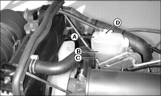
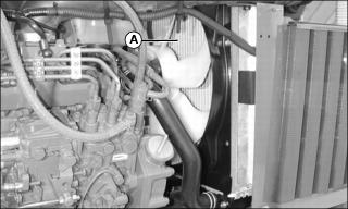
4. Check recovery tank (A) coolant level:
• If engine is warm, coolant level should be between the full line (B) and the low line (C).
• If engine is cold, coolant level should be at the low line (C) on the recovery tank.
5. Remove recovery tank cap (D) if necessary to add coolant.
6. Add pre-diluted coolant or specified ratio of antifreeze and water.
Draining Cooling System
1. Park machine safely. (See Parking Safely in the SAFETY section.)
5. Slowly open radiator cap (A) to the first stop to release all pressure.
6. Close radiator cap tightly.
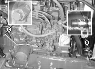
7. Open radiator petcock (B) and drain coolant into a pan.
8. Loosen engine block drain plug (C) and allow all coolant to drain into a pan.
9. When coolant drains from the recovery tank, remove radiator cap.
10. Close radiator petcock and install engine block drain plug.
Flushing Cooling System
1. Fill cooling system with clean water and John Deere Cooling System Cleaner, or John Deere Cooling System Quick Flush or an equivalent. Follow directions on the can.
2. Install and tighten radiator cap.
3. Start and run engine until it reaches operating temperature.
5. Open radiator petcock and remove engine block drain plug.
6. Drain cooling system immediately before rust and dirt settle.
7. Close radiator petcock and install engine block drain plug.
Filling Cooling System
NOTE: John Deere COOL-GARD coolant is recommended when adding coolant to the cooling system.
Follow the directions on the container for correct mixture ratio.
• Cooling system capacity is 5.8 L (6.1 qt).
3. Install and tighten radiator cap.
4. Run engine until it reaches operating temperature.

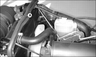
6. Check recovery tank coolant level:
• If engine is warm, coolant level should be between the full line (A) and the low line (B).
• If engine is cold, coolant level should be at the low line (B) on the recovery tank.
7. Remove cap (C) from recovery tank to add coolant if necessary.
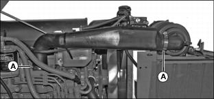
Checking Radiator Hoses and Clamps
1. Park machine safely. (See Parking Safely in the SAFETY section.)
NOTE: Visually inspect hoses for cracks and wear. Squeeze hoses to check for deterioration. Hoses should not be hard and brittle, nor soft or swollen.
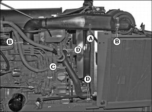
4. Check upper radiator hose (A) for damage or cracking. Replace if necessary.
5. Check hose clamps (B) for looseness. If loose, replace clamps.
6. Check lower radiator hose (C) for damage or cracking. Replace if necessary.
7. Check hose clamps (D) for looseness. If loose, replace clamps.
Servicing Alternator Belt
Checking Belt Tension
1. Park machine safely. (See Parking Safely in the SAFETY section.) Allow engine to cool.
4. Apply moderate thumb pressure to the belt halfway between the pulleys. Belt should deflect inward approximately 9.5 mm (3/8 in.).
5. Adjust belt tension if deflection is more or less than specified.
Adjusting Belt Tension
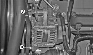
1. Loosen adjusting bolt (A) on alternator on left side of machine.
3. Apply outward pressure to the alternator housing until tension is correct.
6. Replace alternator belt if worn or damaged.
Replacing Belt
NOTE: Replace alternator belt if excessive wear, damage or stretching is detected.
1. Park machine safely. (See Parking Safely in the SAFETY section.) Allow engine to cool.
4. Disconnect black negative (-) cable from battery.

8. Apply inward pressure to alternator housing.
9. Remove belt from alternator sheave, fan sheave and crankshaft sheave.
10. Route defective belt over fan and remove.
11. Install new belt over fan and onto sheaves.
12. Apply outward pressure to alternator housing until tension is correct.
13. Tighten bolt (A) and nut (B).
14. Check belt tension. Adjust as necessary.
15. Connect black negative (-) cable to battery.
Servicing Fuel Filter Sediment Bowl and Replacing Fuel Filter
NOTE: Change filter when fuel is low.
Checking Sediment Bowl
1. Park machine safely. (See Parking Safely in the SAFETY section.) Allow engine to cool.
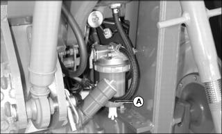
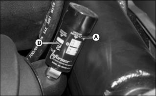
4. Check for visible water and sediment deposits in the sediment bowl (A).
• There is a red ring in the bottom of the sediment bowl which will float on top of any water that is present in the bowl. If the red ring is floating up in the bowl, it is an indication to clean the sediment bowl.
5. If necessary, remove and clean sediment bowl and replace fuel filter.
Cleaning Sediment Bowl and Replacing Fuel Filter
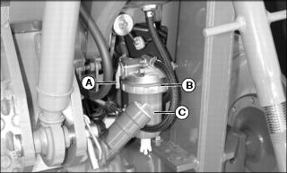
1. Rotate fuel shut-off valve lever (A) to the OFF (horizontal) position.
2. Position drain pan under fuel filter sediment bowl.
3. Turn locking collar (B) counterclockwise to remove bowl (C).
4. Remove and discard the fuel filter.
6. Install new filter to filter head.
7. Install sediment bowl and locking collar.
8. Rotate fuel shut-off valve lever to the ON (vertical) position.
NOTE: Fuel system is self bleeding.
11. Crank engine to bleed fuel system.
Fuel Injection Pump
IMPORTANT: Avoid damage! Do not clean a warm or hot fuel injection pump with steam or water. Clean with compressed air if pump is not cooled. |
NOTE: The fuel injection pump is calibrated by the engine manufacturer and should not require any adjustments.
If engine is hard to start, lacks power, or runs rough, see Troubleshooting Section of this manual.
After performing the check in the troubleshooting section and your engine is still not performing correctly, contact your John Deere dealer.
Fuel Injection Nozzles
If injection nozzles are not working correctly or are dirty, engine will run poorly. See your John Deere dealer for service.
Cleaning Grille and Side Screens
IMPORTANT: Avoid damage! Grille and side screens must be clean to prevent engine from overheating and to allow adequate air intake. |
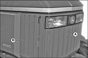
1. Clean grille (A) and side screens (B) with a brush or cloth.
Cleaning Radiator Cooling Screen
• Clear work area of bystanders. • Wear eye protection when using compressed air for cleaning purposes. |
IMPORTANT: Avoid damage! The radiator cooling screen must be clean to prevent engine from overheating and to allow adequate air intake. |
1. Park machine safely. (See Parking Safely in the SAFETY section.) Allow engine to cool.
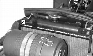
4. Lift tab (A) and remove radiator screen.
5. Clean screen with compressed air, brush or cloth.
Cleaning Radiator Cooling Fins
• Clear work area of bystanders. • Wear eye protection when using compressed air for cleaning purposes. |
1. Park machine safely. (See Parking Safely in the SAFETY section.) Allow engine to cool.
4. Remove radiator cooling screen.
6. Remove all dirt and debris from radiator fins (A) using low pressure compressed air or water. Clean in direction (A), away from engine.
7. Clean radiator cooling screen.
8. Install radiator cooling screen.
9. Install grille and both side panels.
Adjusting Throttle Lever Tension
1. Park machine safely. (See Parking Safely in the SAFETY section.).
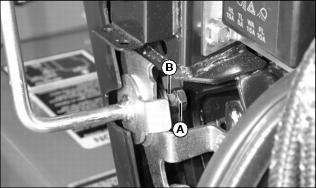
6. Adjust throttle lever friction nut (B):
• Loosen friction nut to decrease drag.
• Tighten friction nut to increase drag.
7. Tighten jam nut (A) to lock the adjustment.