
Service Miscellaneous
Using Proper Fuel (Diesel)
Use the proper diesel fuel to help prevent decreased engine performance and increased exhaust emissions. Failure to follow the fuel requirements listed below can void your engine warranty.
Consult your local fuel distributor for properties of the diesel fuel in your area.
In general, diesel fuels are blended to satisfy the low temperature requirements of the geographical area in which they are marketed.
Diesel fuels specified to EN 590 or ASTM D975 are recommended.
In all cases, the fuel shall meet the following properties:
IMPORTANT: Avoid damage! Improper fuel additive usage may cause damage on fuel injection equipment of diesel engines. |
If a fuel of low or unknown lubricity is used, addition of John Deere PREMIUM DIESEL FUEL CONDITIONER at the specified concentration is recommended.
• Diesel fuel quality and fuel sulfur content must comply with all existing emissions regulations for the area in which the engine operates.
• Use of diesel fuel with sulfur content less than 0.05% (500 ppm) is required.
• Use of ultra-low sulfur diesel fuel with sulfur content less than 0.0015% (15 ppm) is acceptable.
IMPORTANT: Avoid damage! Do not mix diesel engine oil or any other type of lubricating oil with diesel fuel. |
Using Bio-Diesel Fuel
Bio-diesel fuels may be used only if the bio-diesel fuel properties meet the latest edition of ASTM D6751, EN14214, or equivalent specification.
The current maximum allowable bio-diesel concentration is a 5% blend (also known as B5) in petroleum diesel fuel.
To learn of any changes to the recommendations for bio-diesel usage with your diesel engine, ask your John Deere dealer or reference the Services and Support link on the John Deere Commercial and Consumer Equipment website.
Handling and Storing Diesel Fuel
Do not smoke while you fill the fuel tank or service the fuel system. |
• Fill the fuel tank at the end of each day’s operation to prevent water condensation and freezing during cold weather.
• When fuel is stored for an extended period or if there is a slow turnover of fuel, add a fuel conditioner to stabilize the fuel and to prevent water condensation. Contact your fuel supplier for recommendations.
Filling Fuel Tank
Fill fuel tank at the end of each day’s operation to prevent condensation and freezing during cold weather.
1. Park machine safely. (See Parking Safely in the SAFETY section.)
3. Remove any trash from area around fuel tank cap.
4. Remove fuel tank cap slowly to allow any pressure built up in tank to escape.
5. Fill fuel tank only to bottom of filler neck.
Raising and Lowering Hood
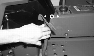
Raise Hood
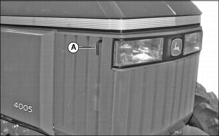
1. Pull hood latch (A) out and lift hood.
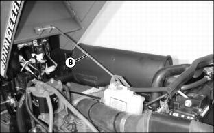
2. Raise hood until support rod (B) slides into locked position.
Lower Hood
1. Lift hood slightly to remove support rod (B) from locked position and lower hood.
2. Push down on front of hood to lock latch.
Removing Side Panels
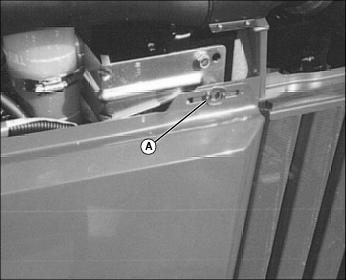
2. Open and turn spring loaded fastener (A) to the horizontal position. Repeat for rear fastener.
3. Lift panel off two lower rod supports to remove.
Checking Tire Pressure
IMPORTANT: Avoid damage! If the tire is liquid filled, always keep the valve stem at the top of the tire when checking tire pressure. This prevents liquid from escaping through the valve stem. |
IMPORTANT: Avoid damage! To prevent tire damage, do not use more than maximum tire pressure shown on sidewall of tire. |
2. Check tire pressure with an accurate gauge.
3. Add or remove air, if necessary.
Checking Wheel Bolt Torque
When machine is new or anytime wheel hardware is loosened, tighten all bolts after one hour of operation and every four hours thereafter until proper torque values are maintained.
Tightness of wheel hardware must be maintained according to service interval recommendations. Check wheel bolt tightness as follows:
Front Wheel Bolts
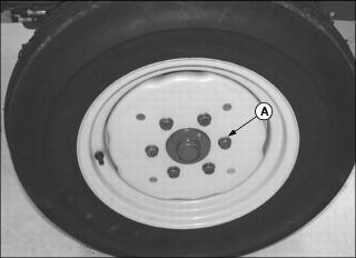
Tighten front wheel disk-to-flange bolts (A) to 155 N•m (114 lb-ft).
2WD Tractors Only: Tighten front axle bolts (B) to 260 N•m (190 lb-ft).
Rear Wheel Bolts
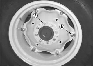
Tighten rear wheel disk-to-flange bolts (A) to 155 N•m (114 lb-ft).
Torque the rear wheel rim-to-disk bolts (B) to 240 N•m (177 lb-ft).
Selecting Front Tire Rolling Direction
• Use a safe lifting device and support machine securely on jack stands. • Block front and rear of wheel not raised to prevent machine movement. |
Machines equipped with directional type tires (such as bar tires) have directional arrows located on the tire sidewall. Under most conditions, tires should be installed with the directional arrow pointing in the direction of travel.
If machine is mainly used for loader operations, lug direction may be reversed to increase tire life and improve traction while backing out of dirt piles.
Move wheel from one side of machine to the other to change tire rolling direction.
Changing Wheel Spacing and Tread Width
To provide best stability, operate machine with rear wheels mounted in the wide tread position whenever possible.
• Use a safe lifting device and support machine securely on jack stands. • Block front and rear of wheel not raised to prevent machine movement. |
IMPORTANT: Avoid damage! Always make sure tires rotate in proper direction. Arrows on sidewall should point in direction of forward rotation. |
The front and rear wheels can be mounted in WIDE or NARROW positions to increase or decrease wheel spacing. To provide best stability, operate tractor with rear wheels mounted in the wide tread position whenever possible.
Front Wheel Positions:
• WIDE POSITION - Install wheel with valve stem to the inside.
• NARROW POSITION - Install wheel with valve stem to the outside.
Rear Wheel Positions:
• WIDE POSITION - Install wheel with valve stem to the outside.
• NARROW POSITION - Install wheel with valve stem to the inside.
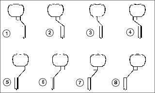
The mounting flanges on the rear rims are closer to one edge of the rim than the other, allowing the inner wheels to be mounted in different positions. By changing this position of the wheel on the rim, up to eight different tread widths can be achieved on some tractors.
Various positions cannot be used because the tires would strike the fenders. Certain other positions may result in equal tread widths.
The front wheel spacing can be adjusted to eight different tread widths by reversing the front wheels and by extending the front axle.
Tread width is measured from centerline-to-centerline of each tire.
Mounting Guidelines
• To keep tire rotation in the proper direction when wheels are reversed without demounting rims, move each wheel to the opposite side of the tractor.
• Rims can be attached to either side of wheel.
• Mounting flanges on rim are closer to one edge of rim.
• Tread width can be changed by turning the wider side in or out.
• To keep tire rotation in the proper direction, move each rim to opposite side of tractor, rather than turning the rims around.
• Dished wheels can be reversed.
• Tighten all bolts to specifications.
Rear Tire Tread Width Dimensions
Front Tire Tread Width Dimensions (2WD Tractors)
Front Tire Tread Width Dimensions (MFWD Tractors)
Checking and Adjusting Toe-In
1. Stop tractor on a firm, level surface.
2. Disengage MFWD if equipped.
3. Turn steering wheel so front wheels are pointing straight ahead.
4. Park machine safely. (See Parking Safely in the SAFETY section.)
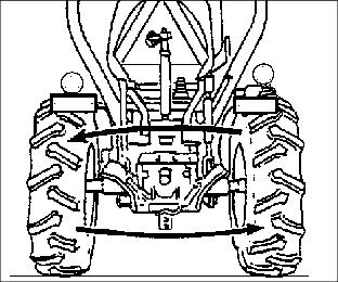
Checking Toe-In
NOTE: If front axle is equipped with bar tires, use an outside bar of each tire or an inside bar of each tire for marking the centerline.
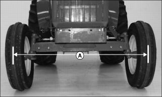
1. Mark the centerline of each tire at hub height and to the front of the axle using chalk.
2. Measure distance (A) between the centerlines of each tire. Record the measurement.
3. Drive tractor forward or rearward slightly until chalk mark moves 180° to the rear of the axle.
4. Park machine safely. (See Parking Safely in the SAFETY section.)
5. Measure distance (A) again between the chalk marks. Record the measurement.
6. Determine the difference between front and rear measurements:
NOTE: If front measurement is smaller, toe is “IN.” If rear measurement is smaller, toe is “OUT.”
• 2WD Tractors - Distance (A) at front of tires should be 3 - 6 mm (1/8 - 1/4 in.) less than distance at rear of tires. If not, adjust toe-in.
• MFWD Tractors - Distance (A) may be larger at front or rear measurement but should not exceed 3 mm (1/8 in.). Adjust toe-in if necessary.
Adjusting Toe-In
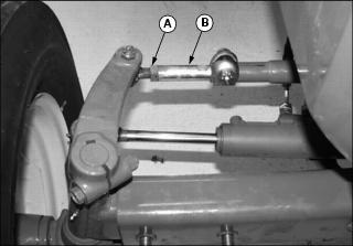
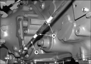
1. Loosen tie rod nut (A) on both tie rod ends.
2. Turn tie rod (B) until toe-in is within correct specification.
3. Tighten both tie rod nuts completely.
Adjusting Front Axle Width
• Use a safe lifting device and support machine securely on jack stands. • Block front and rear of wheel not raised to prevent machine movement. |
Adjust front axle width as needed to achieve desired front tire tread width.
1. Park machine safely. (See Parking Safely in the SAFETY section.)
2. Raise front of tractor with a safe lifting device. Install blocks or safety stands under front frame. Lower tractor onto blocks or stands.
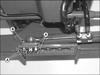
3. Remove four bolts and lock washers (A).
4. Lift power steering cylinder and attached block (B) out of hole in mounting plate so it can move accordingly when front axle is extended.
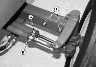
5. Remove cotter pin and nut (C) from tie rod clamp bolt at right side of tractor. Remove tie rod clamp bolt (D).
NOTE: Tie rod and power steering cylinder will self-align to the proper width position as axle is extended.
7. Pull outward on right side wheel assembly to extend the inner axle channel to the desired width. Holes (E) must align with holes in inner axle channel.
8. Install axle bolts (E). Tighten bolts to 260 N•m (190 lb-ft).
NOTE: Steering cylinder block will be self-aligned with one of the adjustment holes (F) in the mounting plate.
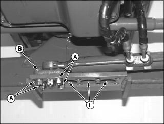
9. Seat block (B) into appropriate adjustment hole (F) in mounting plate.
10. Install four bolts and lock washers (A). Tighten bolts to 78 - 98 N•m (58 - 72 lb-ft).
11. Install tie rod clamp bolt (D). Make sure bolt is seated in adjustment notch in tie rod.
12. Install and tighten nut (C). Secure with cotter pin.
NOTE: Power steering cylinder is adjusted when changing the right front axle. Do not move cylinder when adjusting left front axle.
13. Adjust left front axle in the same manner.
14. Raise front of tractor with a safe lifting device.
15. Remove blocks or stands from under tractor.
18. Check the toe-in setting. Adjust if needed.
Checking and Adjusting Brakes
1. Stop machine on a level surface. Do not lock park brake.
2. Leave machine in gear. Stop engine and remove key.
Checking Brake Adjustment
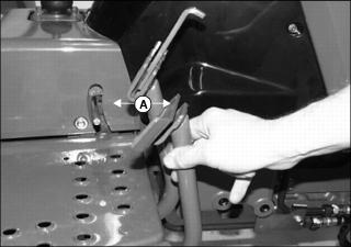
1. Pull down on each brake pedal and measure the free travel distance (A) that the pedal pivots from top of stroke to the point before brake engagement occurs.
2. Adjust both brakes if free travel for either pedal is greater than 35 mm (1-3/8 in.) or if it is not the same for both pedals.
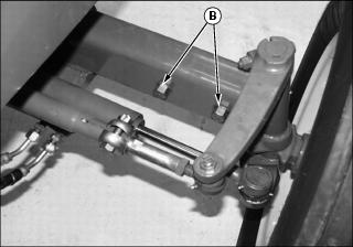
Adjusting Brakes
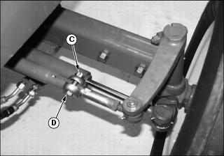
1. Loosen linkage rod lock nuts (A).
NOTE: If brake linkage has no adjustment remaining, see your John Deere dealer for service.
2. Rotate turnbuckle (B) to shorten length of rod (C) so pedal free travel is 25 mm (1 in.).
3. Tighten the lock nuts completely.
4. Repeat for other brake pedal. Adjust to same distance.
Checking and Adjusting Clutch
Checking Clutch Adjustment
1. Pull down on clutch pedal and measure the free travel distance (A) that the pedal pivots from top of stroke to the point before clutch engagement occurs.
2. Adjust clutch if free travel is greater than 25 mm (1 in.).
Adjusting Clutch
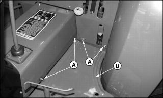
1. Remove screws and flat washers (A) from panels to provide clearance for removal of left footwell plate (B).
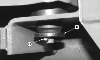
2. Remove cotter pin (C) and rubber washer (D) from three locations at bottom side of footwell plate.
3. Lift and remove footwell plate from tractor.
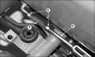
4. Loosen linkage rod lock nuts (E).
NOTE: If clutch linkage has no remaining adjustment, see your John Deere dealer for service.
5. Rotate turnbuckle (F) to shorten length of rod (G) so pedal free travel is 15 - 25 mm (5/8 - 1 in.).
6. Tighten the lock nuts completely.
Cleaning Plastic Surfaces
1. Rinse hood and entire machine with clean water to remove dirt and dust that may scratch the surface.
2. Wash surface with clean water and a mild liquid automotive washing soap.
3. Dry thoroughly to avoid water spots.
4. Wax the surface with a liquid automotive wax. Use products that specifically say “contains no abrasives.”
5. Buff applied wax by hand using a clean, soft cloth.
Cleaning and Repairing Metal Surfaces
Cleaning:
Follow automotive practices to care for your vehicle painted metal surfaces. Use a high-quality automotive wax regularly to maintain the factory look of your vehicle’s painted surfaces.
Repairing Minor Scratches (surface scratch):
1. Clean area to be repaired thoroughly.
2. Use automotive polishing compound to remove surface scratches.
3. Apply wax to entire surface.
Repairing Deep Scratches (bare metal or primer showing):
1. Clean area to be repaired with rubbing alcohol or mineral spirits.
2. Use paint stick with factory-matched colors available from your authorized dealer to fill scratches. Follow directions included on paint stick for use and for drying.
3. Smooth out surface using an automotive polishing compound. Do not use power buffer.