
Operating - Backhoe
Installing and Removing Backhoe
Installing Backhoe
IMPORTANT: Avoid damage! Failure to remove drawbar from machine will result in damage to machine, backhoe, or both. |
1. Remove 3-point hitch and drawbar if installed on machine.
5. Back machine into position to install backhoe.
7. Stop engine. Operator seat should remain facing to the front.
8. Remove retaining pins and attaching pins stored in the backhoe subframe.
IMPORTANT: Avoid damage! To prevent backhoe seal and valve damage, engine must be stopped when connecting hydraulic quick-couplers. |
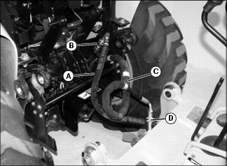
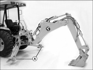
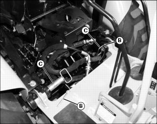
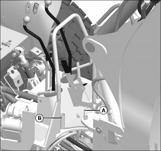
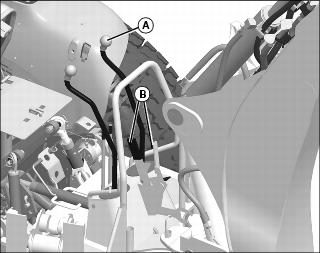
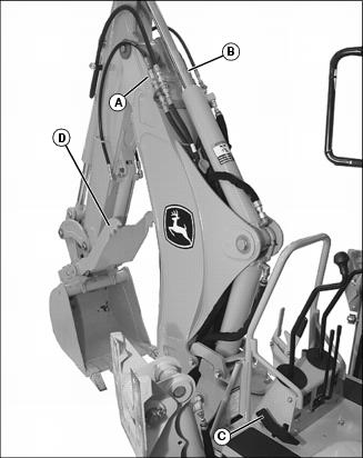
9. Connect hydraulic hose (A) from the backhoe to machine quick coupler (B).
10. Connect hydraulic hose (C) from the machine to backhoe quick coupler (D).
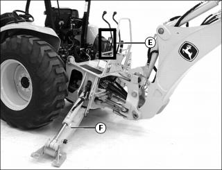
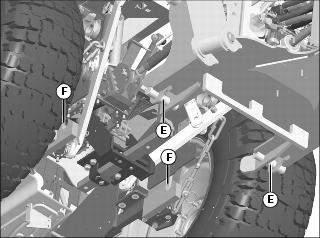
14. Push both stabilizer levers (E) slowly forward to extend stabilizers (F) evenly and raise the backhoe subframe.
IMPORTANT: Avoid damage! Watch hydraulic hoses for pinching and binding while backhoe attachment is being mounted on the machine. Stop procedure and reposition hoses as needed. |
NOTE: When using the repositioning creeper drive speed control, the machine will not move if operator is not positioned on the seat. The machine will stop if operator vacates the seat while machine is in motion.
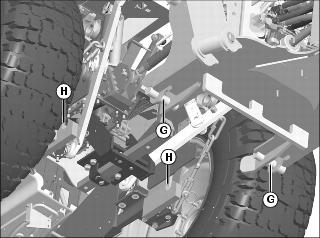
15. Slowly move machine rearward using the repositioning creeper drive speed control lever. The backhoe subframe mounting pins (G) must be aligned directly above the machine mounting hooks (H).
16. Pull both stabilizer levers slowly rearward to retract each stabilizer evenly and pins (G) engage hooks (H).
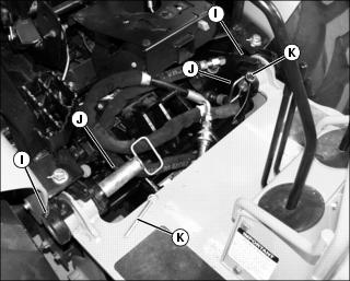
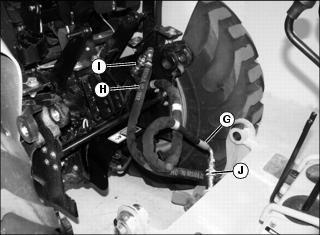
17. Slowly lower backhoe boom to rotate top of subframe forward. Each side of the subframe must engage mounting yokes (I) at the rear of the machine. Continue to lower boom until the rear wheels of the machine are just off the ground and mounting holes are fully aligned.
18. Install attaching pins (J).
19. Install retaining pins (K).
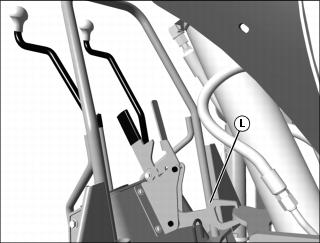
20. Fully retract boom and engage boom lock (L).
21. Fully retract dipperstick and curl bucket.
22. Fully retract stabilizers.
Removing Backhoe
1. Park machine on a hard/ level surface.
2. Lock park brake. Operator seat should remain facing to the front.
5. Extend stabilizers (A) approximately 10 - 15 cm (4 - 6 in.) above the ground.
6. Extend boom and dipperstick slightly. Lower boom to release pressure on attaching pins.
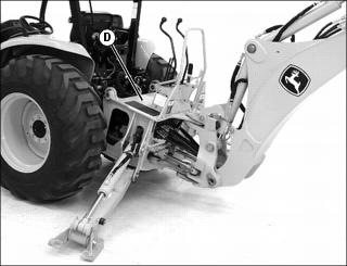
9. Raise boom slowly to rotate top of backhoe subframe (D) away from machine.
10. Install attaching and retaining pins into backhoe subframe for storage.
11. Extend stabilizers evenly to lift subframe pins (E) out of mounting hooks (F).
IMPORTANT: Avoid damage! Watch hydraulic hoses for pinching and binding while backhoe attachment is being mounted on the machine. Stop procedure and reposition hoses as needed. |
NOTE: When using the repositioning creeper drive speed control, the machine will not move if operator is not positioned on the seat. The machine will stop if operator vacates the seat while machine is in motion.
13. Move machine forward slightly using the repositioning creeper drive speed control lever. The backhoe subframe mounting pins must clear the machine mounting hooks.
15. Retract stabilizers slowly and evenly to lower backhoe to ground.
IMPORTANT: Avoid damage! To prevent backhoe seal and valve damage, engine must be stopped when disconnecting the hydraulic quick-couplers. |
IMPORTANT: Avoid damage! To prevent contamination of quick couplers, hose ends should be connected when not being used. |
17. Disconnect hydraulic hoses (G) and (H).
• Connect machine hydraulic hose (G) to machine quick coupler (I).
• Connect backhoe hydraulic hose (H) to backhoe quick coupler (J).
Using Backhoe Swing Frame Lock
Swing Lock
3. Move boom control lever left or right to align lock pin holes.
4. Remove lock pin (A) from storage holder (B) and install in lock hole.
Swing Unlock
1. Move boom control lever slightly left or right to relieve pressure on lock pin (A).
2. Remove lock pin from lock hole and store in holder (B).
Using Backhoe Boom Lock
Boom Lock
3. Pull boom control lever (A) rearward to fully raise boom.
4. Squeeze boom lock handles (B) together to disengage lock mechanism latch.
5. Pull back on handles to engage lock.
Boom Unlock
1. Pull boom control lever (A) rearward to raise boom and relieve pressure on lock mechanism.
2. Squeeze boom lock handles (B) together to disengage lock mechanism latch.
3. Push handles forward to disengage lock.
Using Backhoe Operating Controls
IMPORTANT: Avoid damage! When operating the backhoe and performing a boom swing function, be careful not to swing boom into stabilizers. |
NOTE: The auxiliary hydraulic pressure relief is initially set at 2500 psi. Refer to the attachment operator’s manual for attachment operating pressure. See your John Deere dealer if adjustment is required.
Pedal (C) is used to operate thumb (D) on bucket.
Preparing to Operate Backhoe
1. Back machine close to desired digging location on a hard, level surface.
3. Lower loader and boom to the ground until front tires are off ground.
4. Pivot and lock operator seat into position facing to the rear.
5. Lower stabilizers until rear tires are off ground and machine is level.
6. Remove swing lock pin and store in holder.
8. Check control lever response.
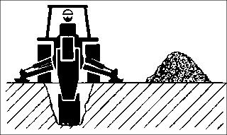
Positioning Spoil Piles
To prevent cave-ins, place spoil pile at least 1 m (3 ft) away from edge of excavation. Deeper excavations require larger area for spoil pile. Place spoil piles in convenient locations for easier truck loading or backfilling.
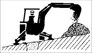
On slopes, place piles on upper side for improved machine stability and easier backfilling.
Leveling Machine
1. Position machine on a hard, level surface when operating the backhoe.
2. Level work area as necessary.
NOTE: When stabilizers are lowered to level machine, they may not be extended the same length due to variations in surface.
3. Extend stabilizers until rear tires are off the ground with minimum clearance between tires and ground.
4. If machine is not level, continue to extend the down slope stabilizer until machine is level side-to-side.
5. With front bucket in dig position, lower until weight of machine is off front tires. Add material in bucket for additional counterweight if needed, especially if backhoe is facing downslope.
6. Position loader in dump position only when loader bucket is lowered level to the ground and will not hold machine steady.
Using Backhoe Bucket
Use type of digging which is best suited for your specific job.
Crowd Digging
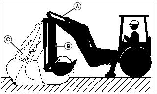
For most general excavating, leveling material, and digging trenches.
Crowd digging utilizes the dipperstick cylinder (A) for majority of movement.
1. Position dipperstick in vertical position (B).
2. Extend dipperstick and extend bucket simultaneously approximately 0.61 m (2 ft) (C) away from machine.
3. Retract dipperstick and curl bucket simultaneously back to vertical (B), to make first cut. First cut should be approximately 1.2 m (4 ft) long and 75 - 100 mm (3 - 4 in.) deep.
4. Repeat steps 1 and 3 for remaining cuts and increase depth to 100 - 150 mm (4 - 6 in.) deep.
Bucket Digging
For power digging or working in small areas.
Uses bucket cylinder (A) for digging.
1. Extend bucket and dipperstick to dig point.
2. Lower bucket into digging area using boom to force bucket into ground.
3. Retract dipperstick and curl bucket simultaneously until bucket is full.
If bucket stalls, raise the boom slightly and continue to curl bucket.
If dipperstick stalls, roll back bucket then raise boom slightly to break out.
Using a Sight Gauge for Trenching
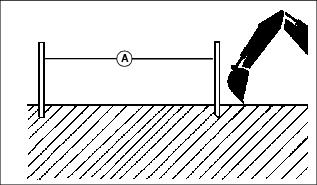
Drive two stakes in ground, 9 m (30 ft) apart (A), in line with desired trench location. Use stakes as a sight gauge. Use of a sight gauge is recommended especially if machine is moved off course often.
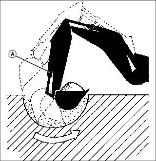
Trenching
Trenches should be dug with walls angled outward to prevent cave-ins.
If cave-in occurs and cannot be reached from current position, drive machine to side of cave-in, and park at a 90° angle to trench.
Operating Dipperstick with Attachments
Operating hydraulic attachments such as hammers or compactors with dipperstick extended may cause abnormal wear and stress on dipperstick components and ultimately shorten their life. When operating these types of attachments, keep dipperstick as close to vertical as possible.
Installing and Removing Backhoe Attachment with Standard Pin-On System
Installing Attachment
1. Remove cotter pins (A), washers (B) and pin fasteners (C) stored in dipperstick arm.
2. Lower boom to align dipperstick arm mounting holes and attachment mounting holes.
3. Install pin fasteners (C) through attachment and dipperstick arm mounting holes. Secure each side of attachment with washers (B) and cotter pins (A).
Removing Attachment
1. Lower attachment onto a hard, level surface.
2. Remove cotter pins (A), washers (B) and pin fasteners (C).
4. Install pin fasteners, washers and cotter pins in dipperstick arm mounting holes for storage.
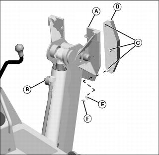
Installing and Removing Backhoe Attachment with Quick Couple System
Installing Attachment
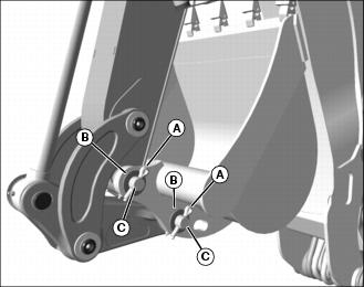
1. Align dipperstick arm with attachment to be installed.
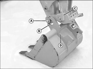
Picture Note: Bucket attachment shown.
2. Begin sliding boom pin (A) into attachment mounting groove (B). Extend the bucket cylinder (bucket curl) to lower boom wedge (C) into slot (D).
Picture Note: Bucket attachment shown.
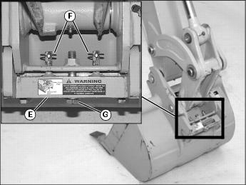
3. Install wedge bar (E), lynch pins (F), and wedge bar bolt (G).
4. Tighten wedge bar bolt (G) to 135.5 N•m (100 lb-ft).
Removing Attachment
1. Park machine safely. (See Parking Safely in the SAFETY section.)
2. Position bucket flat on ground.
3. Loosen wedge bar bolt (G) eight to ten turns.
4. Loosen wedge bar (E) with a pry bar.
5. Remove wedge bar bolt (G), lynch pins (F), and wedge bar (E).
6. Retract bucket cylinder to release mounting wedge (C) from slot (D).
7. Retract dipperstick to release boom pin (A) from mounting groove (B).
Using Bucket Thumb
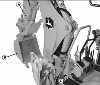
Use bucket thumb (A) to immobilize item(s) in bucket (B).
To rotate thumb towards bucket, push on front of pedal (C). To release thumb, push on back of pedal (C).
Using Backhoe Stabilizer Feet
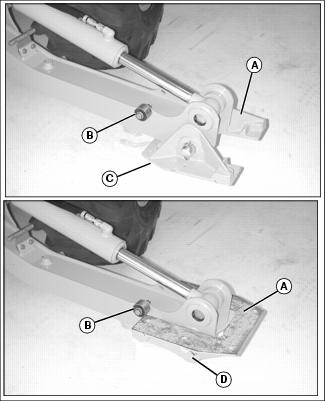
1. Rotate foot (A) past roller (B) to use flat side (C) of stabilizer foot when operating on hard surfaces.
2. Rotate foot (A) past roller (B) to use cleat side (D) of stabilizer foot when operating in dirt.
Installing Stabilizer Rubber Foot Pads
1. Raise both backhoe stabilizers.
2. Park machine safely. (See Parking Safely in the SAFETY section.)
3. Rotate each stabilizer foot (A) past roller (B) to expose flat side of foot.
4. Align foot pad mounting studs (C) and stabilizer foot mounting holes.
5. Fasten each pad (D) to stabilizer foot with three washers (E) and nuts (F).