
Service Miscellaneous
Using Proper Fuel (Diesel)
Use the proper diesel fuel to help prevent decreased engine performance and increased exhaust emissions. Failure to follow the fuel requirements listed below can void your engine warranty.
Consult your local fuel distributor for properties of the diesel fuel in your area.
In general, diesel fuels are blended to satisfy the low temperature requirements of the geographical area in which they are marketed.
Diesel fuels specified to EN 590 or ASTM D975 are recommended.
In all cases, the fuel shall meet the following properties:
IMPORTANT: Avoid damage! Improper fuel additive usage may cause damage on fuel injection equipment of diesel engines. |
If a fuel of low or unknown lubricity is used, addition of John Deere PREMIUM DIESEL FUEL CONDITIONER at the specified concentration is recommended.
• Diesel fuel quality and fuel sulfur content must comply with all existing emissions regulations for the area in which the engine operates.
• Use of diesel fuel with sulfur content less than 0.05% (500 ppm) is required.
• Use of ultra-low sulfur diesel fuel with sulfur content less than 0.0015% (15 ppm) is acceptable.
IMPORTANT: Avoid damage! Do not mix diesel engine oil or any other type of lubricating oil with diesel fuel. |
Using Bio-Diesel Fuel
Bio-diesel fuels may be used only if the bio-diesel fuel properties meet the latest edition of ASTM D6751, EN14214, or equivalent specification.
The current maximum allowable bio-diesel concentration is a 5% blend (also known as B5) in petroleum diesel fuel.
To learn of any changes to the recommendations for bio-diesel usage with your diesel engine, ask your John Deere dealer or reference the Services and Support link on the John Deere Commercial and Consumer Equipment website.
Handling and Storing Diesel Fuel
Do not smoke while you fill the fuel tank or service the fuel system. |
• Fill the fuel tank at the end of each day’s operation to prevent water condensation and freezing during cold weather.
IMPORTANT: Avoid damage! The fuel tank is vented through the filler cap. If a new cap is required, always replace it with an original vented cap. |
• When fuel is stored for an extended period or if there is a slow turnover of fuel, add a fuel conditioner to stabilize the fuel and to prevent water condensation. Contact your fuel supplier for recommendations.
Filling Fuel Tank
Fill fuel tank at the end of each day’s operation to prevent condensation and freezing during cold weather.
1. Park machine safely. (See Parking Safely in the SAFETY section.)
3. Remove any trash from area around fuel tank cap.
4. Remove fuel tank cap slowly to allow any pressure built up in tank to escape.
5. Fill fuel tank only to bottom of filler neck.
Raising and Lowering Hood
Raising
1. Park machine safely. (See Parking Safely in the SAFETY section.)

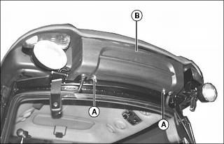
2. Lift either hood release lever (A).
3. Raise hood (B), and raise support rod (C) to secure into bracket hole (D).
Lowering
1. Lift hood slightly to remove weight from support rod (C).
2. Release support rod from bracket hole (D), and lower support rod to latch on machine frame.
4. Push down on front of hood to lock the latch.
Servicing Air Conditioner
Air Conditioner Checks
Check the following if air conditioner will not cool, or if cooling is intermittent:
IMPORTANT: Avoid damage! R134a refrigerant must be used. This requires special equipment and procedures. See your John Deere dealer. |
NOTE: Some oil seepage from compressor shaft seal, on the lower front, is normal.
1. If air conditioner clutch slips after tractor has been in storage, compressor may be stuck.
• Stop engine and turn ignition switch to stop (off) position.
• Raise hood and rotate clutch hub back and forth to free compressor.
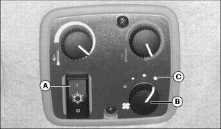
2. Run engine at 2000 rpm. Push top half of A/C and defrost switch (A) and set blower control knob (B) to high position (C). If cooling is intermittent, clean hood grille, radiator and condenser. If problem is not solved, see your John Deere dealer.
3. Inspect operator enclosure (cab) filter for restriction. If problem persists, see your John Deere dealer to have evaporator core cleaned.
Cleaning Air Conditioner Condenser
• Clear work area of bystanders. • Wear eye protection when using compressed air for cleaning purposes. |

1. Raise hood, remove screen (A), and check air conditioner condenser (B) for dirt and debris. Clean condenser using a brush or compressed air.
2. If a more thorough cleaning is necessary, clean radiator from behind with compressed air or water. Straighten any bent fins.
Cleaning Cab Air Filter
IMPORTANT: Avoid damage! Remove any rear implement before servicing cab air filter. Do not stand on 3-point hitch, drawbar hitch or PTO shield. |
1. Remove two wing bolts (A), washers, and filter base (B).
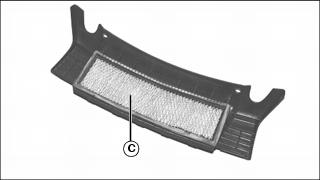
2. Remove filter (C) from filter base, and clean with compressed air. Inspect filter for damage. Replace if necessary.
3. Install filter back into filter base.
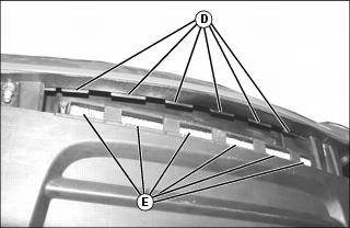
4. Install filter base, making sure six tabs (D) on roof panel are installed into slots (E) in filter base. Secure base assembly back into roof panel with two washers and wing bolts.
Checking Cab Rollover Protection System Installation
• Do not repair or revise the ROPS. • Any alteration of the ROPS must be approved by the manufacturer. |
1. When installation of equipment on a machine necessitates loosening or removing cab protection system, mounting capscrews should be tightened to specification.
2. Inspect cab protection system mounting hardware every 50 hours for proper torque or replacement.

3. Lift up rubber floor mat (A) to access FRONT mounting hardware.
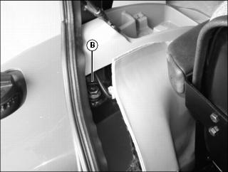
4. Remove fastener and pull insulation liner away from fender to access REAR mounting hardware (B).
5. Tuck the insulation liner under the fender panels when complete.
6. Tighten the mounting hardware to 260 N•m (192 lb-ft).
Checking Wheel Bolts and Hardware
When machine is new or anytime wheel hardware is loosened, tighten all bolts after one hour of operation and every four hours thereafter until proper torque values are maintained.
Tightness of wheel hardware must be maintained according to service interval recommendations. Check wheel bolt tightness as follows:
Front Wheel Bolts
Tighten front wheel bolts alternately to 140 N•m (103 lb-ft).
Rear Wheel Bolts
Tighten rear wheel bolts alternately to 140 N•m (103 lb-ft).
Removing and Installing Wheels
• Use a safe lifting device and support machine securely on jack stands. • Block front and rear of wheel not raised to prevent machine movement. |
Front Wheel Removal
1. Loosen lug nuts slightly before raising front axle.
2. Raise front of machine and lower onto support stands so that machine is supported by front axle.
3. Remove lug bolts and wheel.
NOTE: If the front wheels are being removed to perform work on the front axles, lower machine onto suitable stands that will support the machine by the frame.
Front Wheel Installation
1. Install wheels onto axle, insert lug bolts and lightly tighten bolts.
2. Raise front of machine, remove support stands and lower machine to floor.
3. Tighten lug bolts to 140 N•m (103 lb-ft).
Rear Wheel Removal
1. Loosen lug bolts slightly before raising machine rear axle.
2. Raise rear of machine and lower onto support stands so that machine is supported by rear axle.
3. Remove lug bolts and wheel.
Rear Wheel Installation:
1. Install wheels onto axle, insert lug bolts and lightly tighten bolts.
2. Raise rear of machine, remove support stands and lower machine to floor.
3. Tighten lug bolts to 140 N•m (103 lb-ft).
Checking Tire Pressure
2. See tire pressures in SPECIFICATIONS.
3. Check tire pressure with an accurate gauge.
4. Add or remove air, if necessary
Selecting Front Tire Rolling Direction
• Use a safe lifting device and support machine securely on jack stands. • Block front and rear of wheel not raised to prevent machine movement. |
Machines equipped with directional type tires (such as bar tires) have directional arrows located on the tire sidewall. Under most conditions, tires should be installed with the directional arrow pointing in the direction of travel.
If machine is mainly used for loader operations, lug direction may be reversed to increase tire life and improve traction while backing out of dirt piles.
Move wheel from one side of machine to the other to change tire rolling direction.
Changing Wheel Spacing and Tread Width
The front and rear wheels can be mounted in wide or narrow positions to increase or decrease wheel spacing. To provide best stability, operate machine with rear wheels mounted in the wide tread position whenever possible.
• Use a safe lifting device and support machine securely on jack stands. • Block front and rear of wheel not raised to prevent machine movement. |
IMPORTANT: Avoid damage! Always make sure tires rotate in proper direction. Arrows on sidewall should point in direction of forward rotation. |
Front Wheel Positions:
• Wide position - Install wheel with valve stem to the inside.
• Narrow position - Install wheel with valve stem to the outside.
Rear Wheel Positions:
• Wide position - Install wheel with valve stem to the inside.
• Narrow position - Install wheel with valve stem to the outside.
For 8 position wheels, the mounting flanges on the rear rims are closer to one edge of the rim than the other, allowing the inner wheels to be mounted in different positions. By changing this position of the wheel on the rim, up to eight different tread widths can be achieved on some machines.
Various positions cannot be used because the tires would strike the fenders. Certain other positions may result in equal tread widths.
Tread width is measured from centerline-to-centerline of each tire.
Mounting Guidelines
• To keep tire rotation in the proper direction when wheels are reversed without removing tires from rims, move each wheel to the opposite side of the machine.
• Rims can be attached to either side of wheel.
• Mounting flanges on rim are closer to one edge of rim.
• Tread width can be changed by turning the wider side in or out.
• To keep tire rotation in the proper direction, move each rim to opposite side of machine, rather than turning the rims around.
• Dished wheels can be reversed.
• Tighten all bolts to specifications.
Rear Tire Tread Width Dimensions

Front Tire Tread Width Dimensions
* Do not install tires with chains in this position.
NOTE: Do not install tire chains on 13.6-28 R1 tires installed on tractor models 4120-4720 with a cab.
Cleaning Plastic Surfaces
1. Rinse hood and entire machine with clean water to remove dirt and dust that may scratch the surface.
2. Wash surface with clean water and a mild liquid automotive washing soap.
3. Dry thoroughly to avoid water spots.
4. Wax the surface with a liquid automotive wax. Use products that specifically say “contains no abrasives.”
5. Buff applied wax by hand using a clean, soft cloth.
Cleaning and Repairing Metal Surfaces
Cleaning:
Follow automotive practices to care for your vehicle painted metal surfaces. Use a high-quality automotive wax regularly to maintain the factory look of your vehicle’s painted surfaces.
Repairing Minor Scratches (surface scratch):
1. Clean area to be repaired thoroughly.
2. Use automotive polishing compound to remove surface scratches.
3. Apply wax to entire surface.
Repairing Deep Scratches (bare metal or primer showing):
1. Clean area to be repaired with rubbing alcohol or mineral spirits.
2. Use paint stick with factory-matched colors available from your authorized dealer to fill scratches. Follow directions included on paint stick for use and for drying.
3. Smooth out surface using an automotive polishing compound. Do not use power buffer.