
Installing
Attaching Backhoe to Tractor (3000 and 4000 Series)
1. Review instructions on using rockshaft control lever included in your tractor operator’s manual.
2. Lock folding ROPS in full upright position.
3. Close and lock cab rear window.
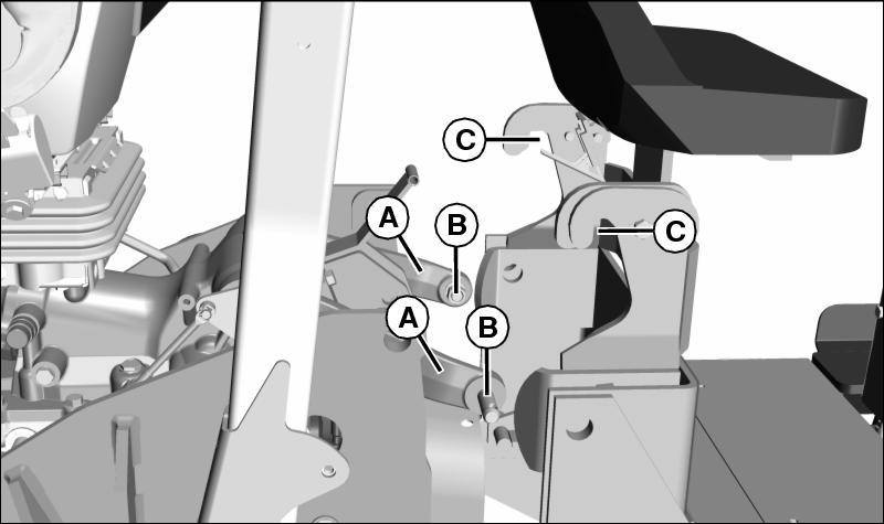
Picture Note: Tires and fenders removed.
4. Fully lower tractor rockshaft arms (A). Align rockshaft pins (B) with hooks (C) on backhoe, and back tractor into position.
5. Check to be sure backhoe hydraulic hoses are clear of backhoe hooks and hardware.

Picture Note: Tires and fenders removed.
6. Slowly lift rockshaft arms, making sure pins engage into hooks on backhoe. Check to be sure both lower pins (D) on backhoe engage both hooks (E) on tractor RSA mounting plates.

Picture Note: Tractor seat removed.
7. Fully raise rockshaft arms so stop (F) is against edge of RSA mounting plates.

8. Install L-pins (G) in backhoe and RSA mounting plates. If backhoe and RSA mounting plates do not align, and L-pins do not slide in and out easily, lower backhoe to ground and adjust movable latch plates (H). Left and right movable latch plates may need different adjustment.
9. Install hitch pins in L-pins.
11. Lower the rockshaft to transfer weight of backhoe from rockshaft arms to L-pins.
Attaching Backhoe to Tractor (5000 Series)
1. Review instructions on using rockshaft control lever included in your tractor operator’s manual.
2. Lock folding ROPS in full upright position.
3. Close and lock cab rear window.
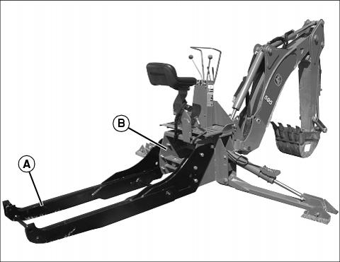
4. Position rear of tractor at front of subframe (A).
5. Slowly move tractor rearward over subframe, leaving approximately 610 mm (24 in.) of space between rear of tractor and backhoe platform (B).
6. Place tractor in park, shut OFF engine, and remove key. Place wheel chocks in front of and behind rear wheels.
IMPORTANT: Avoid damage! Power beyond hydraulic kit must be installed on tractor to operate backhoe attachment. See your John Deere dealer. |


7. Connect backhoe hydraulic supply hose (C) to female coupler (D) on power beyond panel (E).
8. Connect elbow fitting (F) on opposite end of backhoe hydraulic return hose (G) to male coupler (H) on power beyond extension hose (I).

9. Start tractor and use backhoe hydraulic controls to raise subframe (A) until rear crossbar (J) is in line with rear mount slots (K).
10. Slowly move tractor rearward until crossbar is fully engaged in rear mount slots. Place tractor in park.
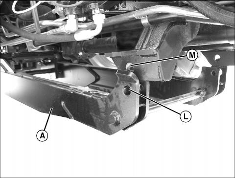
11. Using backhoe hydraulic controls, pivot front of subframe (A) until front holes (L) on subframe are aligned with holes (M) on front hanger. Shut OFF engine.
12. Install tapered pins through holes in subframe and front hanger.
13. Install quick-lock pins through tapered pins.
Routing Hydraulic Hoses (485)

1. Position drain pan and remove male coupler (A) from 90? elbow on backhoe pressure hose.

2. Route backhoe pressure hose (B) up through backhoe right side.
3. Install male coupler back on 90? elbow.
4. Route backhoe return hose (C) up through backhoe left side. It may be necessary to remove the female coupler to allow the hose to fit.
Connecting Hydraulic Hoses (3000 and 4000 Series)
1. Stop engine and park tractor safely with L-pins installed in backhoe.
2. Cycle the rockshaft control lever to relieve all pressure on rockshaft.

Picture Note: Large chassis tractor no cab.

Picture Note: Mid chassis tractor no cab..
3. Disconnect Power Beyond hose (A) from female coupler (B). Install dust cap (C) on hose, and lay hose aside on backhoe frame.
4. Connect backhoe return hose with female coupler to fitting (D).
5. Connect backhoe pressure hose with male coupler to female coupler (B).