
Assembly
Parts in Lift Kit
NOTE: Some parts are installed on tractor, and others are installed on mower.
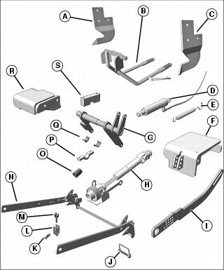
* Quantity used will depend on tractor with grille guard application.
** Parts will be installed on mower deck.
Assemble Mower
Install Wheels
NOTE: 60D mower includes two offset wheels which are to be installed on right side of mower; 72D mower wheels are all the same.
1. Remove mower from crate using chain hoist or other suitable device.

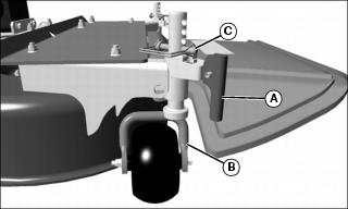
• Install spring (A) in bracket as shown.
• Push wheel lock assembly (B) into bracket.
• Install roll pin (C) to secure wheel lock assembly.
NOTE: After wheels are installed, it may be necessary to lock wheels by pressing downward on handles (A) until they are perpendicular to ground. However, wheels must be in the unlocked position before installing mower on tractor.
Picture Note: 60D mower offset wheels shown installed on right side of mower.
3. Install wheels (B) by sliding wheel shaft up through wheel bracket.
4. Install spring pin (C) in each wheel.
Install Discharge Chute
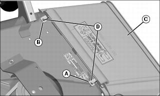
Picture Note: 72D mower shown.
1. Attach rear hinge (A) to deck with nut. Do not tighten.
2. Pre-load spring with one hand and attach front hinge (B) to deck with nut. Do not tighten.
3. Pull chute assembly (C) away from deck as nuts (D) are tightened to help align hinges.
Install Mower Lift Kit
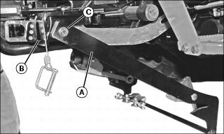
Install Forward Lift Link on Mower Deck
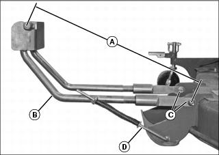
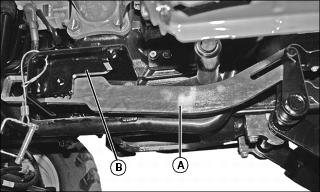
1. Measure distance (A) from center of horizontal frame to center of bolt. Distance (A) should be 599 mm (23.6 in.).
2. Secure forward lift link (B) to mower deck with two M12x50 flange head bolts and two locknuts (C). Adjust as necessary to obtain correct distance before tightening locknuts completely.
3. Insert end of rod (D) in slot with front link raised so spring is fully extended.
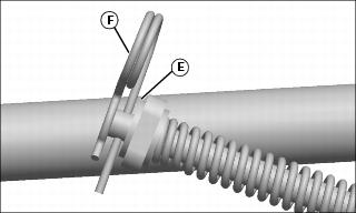
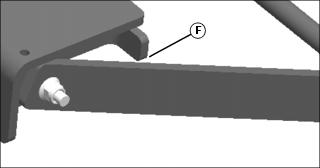
4. Tractors with loader installed: Loader components may hit forward link when removing mower. During initial set up, add washers (E) as needed to prevent contact with loader componenets.
a. Remove hair pin (F) from top of rod.
b. Add washers (E) as needed to prevent contact with loader components.
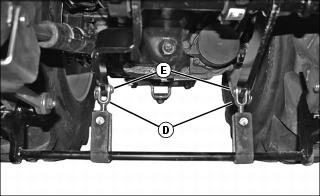
Assemble Rear Lift Link
NOTE: If installing kit on tractor with cab, a lock (A) and roll pin (B) must be ordered separately.
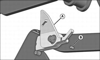
Picture Note: Image shown from inside of rear lift link. Lock is show in the install/locked position.
1. Tractors with cab: Replace lock on left side of rear link with new lock (A). Push roll pin in from outside of rear lift link. Roll pin should clear sheet metal tab on new lock.
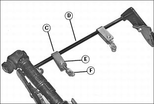
2. Install two U-brackets (C) on rear lift link (D) with two link pins (E) and adjustable yokes (F).
Install Hangers (Tractors without Front Hitch)

Picture Note: Hangers shown on tractor with grille guard.
a. Install left hanger (A) on inside of tractor frame with one M12x45 flange head bolt (B), two M12x65 flange head bolts (C) and three M12 locknuts.
2. Tractor without grille guard:
a. Install left hanger (A) on inside of tractor frame with three M12x45 flange head bolts (B and C) and M12 locknuts.
3. Push bottom of hangers fully rearward and tighten hardware to 130 N•m (96 lb-ft).
Install Hangers (Tractors with Front Hitch)
NOTE: Hangers included in this kit are intended for use on tractors without front hitch. If kit is being installed on tractor with front hitch, different hangers must be purchased and installed. See your John Deere Dealer.
1. Fully lower front hitch using hydraulics.
2. Completely close flow valve.
3. Disconnect front hitch hoses from SCV and tie out of way.
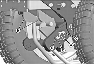
4. Remove locking rings (A) securing hitch arms to front hitch structure.
5. Pull brackets (B) and pins (C) out enough to insert new hangers (D).
6. Push pins (C) through holes in hangers and replace locking rings (A).
Install Brackets
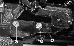
1. Install right bracket (A) on tractor with one M12x30 hex head bolt (B) and one M12x30 hex socket head bolt (C). Push bracket fully forward and tighten hardware.
2. Remove bolt (D) and spacer (E) from suction side filtration tube at left side of tractor.
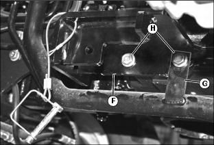
3. Slide edge of right bracket (F) behind tab (G). Push bracket fully forward and secure with two M12x30 hex head bolts (H).
Install Mid Rockshaft
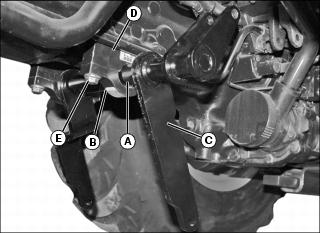
1. Position rockshaft bushings (A) with flange end facing centerline of tractor, and between half clamp (B) and mid rockshaft (C).
2. Position block clamp (D) on top of mid rockshaft and install all parts to tractor with four M12x90 hex head bolts (E).
3. Tighten bolts to 130 N•m (96 lb-ft).
Install Height Adjust Link
1. Slide height adjust link (A) in left bracket (B).
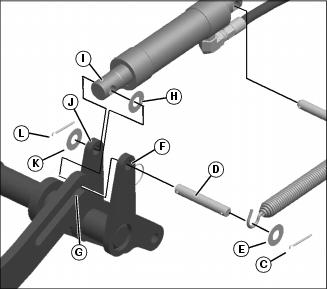
2. Install cylinder rod end and height lock link to rockshaft. Insert cotter pin (C) into end of rockshaft pin (D). Push pin through washer (E), first arm of rockshaft (F), slot in height lock link (G), washer (H), rod end of cylinder (I), second arm on rockshaft (J) and final washer (K). Secure with cotter pin (L). Make sure washers are installed as shown.
NOTE: If installing lift kit on tractor with cab, a separate bracket must be purchased before cylinder can be installed.
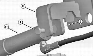
3. Tractor with cab: Attach head end of cylinder (G) to bracket (H) with M12x70 drilled pin (I) and locking ring (J).
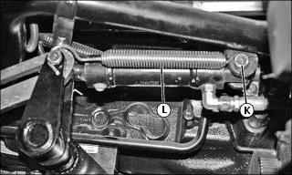
4. Secure other end of cylinder with M12x70 drilled pin (K), washer and cotter pin.
5. Install spring (L) with spring rotation down.
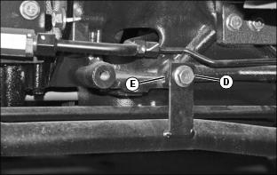
Complete Installation of Lift Kit
1. Secure rear lift link (A) to left bracket (B) with one M12x50 flange bolt, one bushing and one M12 locknut (positioned at outside of lift link) (C).
2. Secure rear lift link to right bracket.
3. Attach adjustable yokes (D) to mid rockshaft with two M12x35 drilled pins (E) and locking rings.
5. Either route hydraulic cylinder hose to rear of tractor and attach to third SCV, or attach it to curl circuit on dual SCV.
6. Install one hair pin in rear hole on right arm of rear lift link. Install hair pin in hole in left bracket.
7. Start tractor and slowly raise lift system. Arms of rear link should clear up-stops at rear of brackets mounted on transmission by 1-2 mm (0.04 - 0.08 in.) (F).


