Assembly
Parts in Kit
54D Mower Deck
60D Mower Deck
Assemble Mower
Before installing the mower, the following equipment must be installed on the machine. See your John Deere dealer.
• Mower Lift Kit (Mechanical or Hydraulic)
• Mower Driveshaft Kit (Standard or AutoConnect™)
Install Wheels
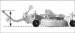
1. Remove mower from crate using chain hoist or other suitable device.
NOTE: After wheels are installed, it may be necessary to lock wheels by pressing downward on handles (A) until they are perpendicular to ground. However, wheels must be in the unlocked position before installing mower on tractor.
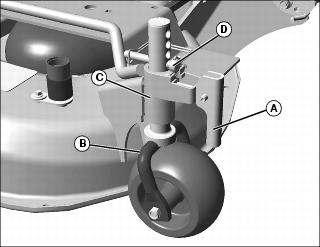
2. Install wheels (B) by sliding wheel shaft up through wheel bracket (C).
3. Install spring pin (D) in each wheel shaft.
Install Gearbox (54D)
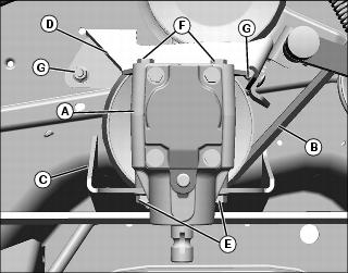
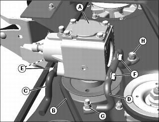
1. Lower gearbox assembly (A) onto mower while routing belt (B) around gearbox pulley and between legs of gearbox brackets (C, D) as shown. Removal of bracket (D) from mower may be required for belt routing.
2. Loosely install two M10x25 bolts (E) through front bracket (C) into gearbox.
3. Loosely install two M10x25 bolts (F) through rear bracket (D) into gearbox.
4. Tighten four M10 gearbox mounting bolts (E, F) to 73 N•m (54 lb-ft).
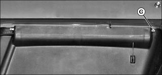
5. Tighten two rear gearbox mounting bracket nuts (G) to 73 N•m (54 lb-ft).
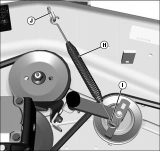
6. Attach spring (H) to tensioner arm (I) and bracket (J) on mower.
7. Check all pulleys for proper belt alignment.
Install Gearbox (60D)
1. Lower gearbox assembly (A) onto mower while routing belt (B) around gearbox pulley and between legs of gearbox brackets (C, D) as shown.
2. Loosely install two M10x25 bolts (E) through front bracket (C) into gearbox.
3. Loosely install two M10x25 bolts (F) through rear bracket (D) into gearbox.
4. Tighten four M10 gearbox mounting bolts (E, F) to 73 N•m (54 lb-ft).
5. Tighten rear gearbox mounting bracket nuts:
a. Tighten one M10 nut (G) to 73 N•m (54 lb-ft).
b. Tighten one M12 nut (H) to 119 N•m (88 lb-ft).
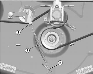
6. Attach spring (I) to tensioner arm (J) and bracket (K) on mower.
7. Check all pulleys for proper belt alignment.
Install Discharge Chute (54D)
NOTE: Ensure correct placement of spring (A) to provide downward pressure on discharge chute.
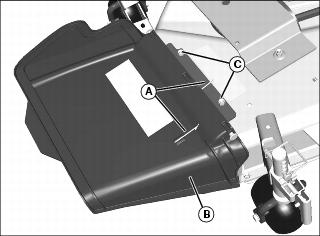
1. Position the discharge chute assembly (B) on the mower and secure with two M8x16 carriage head bolts and two M8 locknuts (C).
Install Discharge Chute (60D)

2. Install rod though first chute hole (B), first mower attaching point (C), second chute hole (D) and spring (E).
NOTE: Correct placement of spring is necessary to provide downward pressure on discharge chute.
Picture Note: View from front of mower.
3. Insert long end (F) of spring through hole in discharge chute and push pin into spring.
4. Unwind short end of spring until it can be placed on top of mower.
5. Insert rod through remaining mower and discharge chute attaching points.
6. Verify that spring placement is correct by ensuring discharge chute has downward pressure.
7. Install roll pin (G) at end of rod.
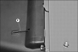
Install Front Draft Link
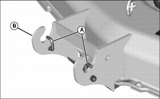
1. Remove nut and lock pin (A) from each side of front draft link bracket (B).
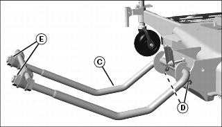
2. Install draft link assembly (C) in bracket and secure with two lock pins and nuts (D).
3. Loosen front nuts (E) on draft link assembly 4-5 turns (Nuts will be tightened when mower is initially installed on machine).
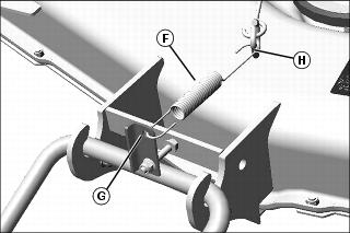
4. Install spring (F) through hole in draft link bracket (G) and ring on mower (H).