
Operating
Raising and Lowering Mower
The machine can be equipped with a mechanical or hydraulic mower lift control system. The height-of-cut control is the same for both systems. All controls are described below.
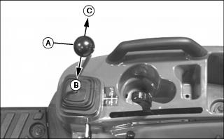
Mechanical Lift System

A mechanical mower lift kit is connected to the machine rock shaft and operates with the rock shaft control lever (A). See Using 3-Point Hitch - Using Rockshaft Control Lever in the machine Operator’s Manual for operating instructions for your specific model.
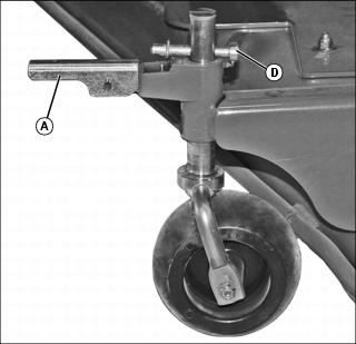
Hydraulic Mower Lift System
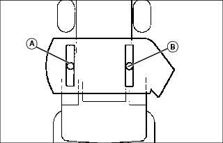
A hydraulic mower lift system operates independently of the machine rockshaft and is operated by the machine SCV lever (A).
Review Using Hydraulic Dual SCV instructions in the machine operator’s manual.
• Pull the SCV lever to the left (B) to raise the mower.
• Make any adjustment required to the height-of-cut control.
• Push the SCV lever slightly to the right (C) to lower the mower. Do not push the lever fully to the right, to avoid engaging the Regen function of the hydraulic circuit resulting in unintended motion.
Height-of-Cut Adjustment
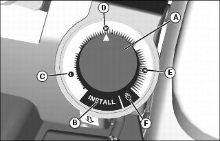
The mower height-of-cut is adjusted with the control (A) on the left side of the operator.
Raise and hold the mower to its highest position using either type of lift system and adjust the height-of cut control as follows:
• Install (B) - Turn the control to this position to lower the mower lift mechanism whenever removal or installation of the mower is required.
• Height-of-Cut Range (C-E) - Turn the control to any position in this range to select the desired height-of-cut.
• Lock (F) - Raise mower and turn control to this position to lock the mower into the highest position on the machine.
Adjusting Mower Level (Side-to-Side)
1. Park machine on a level surface, not on a slope.
4. Raise mower, turn the height-of-cut control to the desired cutting height and lower mower.
5. Stop engine and remove key.
6. Wait for engine and all moving parts to stop before leaving operator’s seat.
NOTE: Mower wheels should not contact ground during leveling.
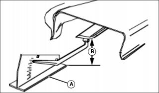
Picture Note: A convenient leveling gauge (A) (AM130907) is available from your dealer.
7. Position mower blades as follows and measure from each outside blade tip to the level surface (B).
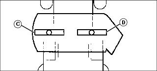
8. Turn left blade (C) as shown. Hold drive belt and turn right blade (D) as shown. Take blade tip to surface measurement on both blades.
• The difference between both measurements must not be greater than 3 mm (1/8 in.).
9. To adjust side-to-side level:
a. Remove retaining pins (E) from left and right rear turnbuckles (F).
b. Adjust one turnbuckle at a time as required and check blade level.
c. When adjustment is complete, install retaining pin(s).
Adjusting Mower Level (Front-to-Rear)
1. Park machine on a level surface, not on a slope.
4. Raise mower, turn the height-of-cut control to the desired cutting height and lower mower.
5. Stop engine and remove key.
6. Wait for engine and all moving parts to stop before leaving operator’s seat.
NOTE: Mower wheels should not contact ground during leveling.
7. Turn left blade (A) as shown. Hold drive belt and turn right blade (B) as shown. Take blade tip to surface measurement on both ends of each blade.
NOTE: Front of mower blades should never be higher than rear of mower blades.
• For best cut quality, the front blade tips must be 3- 6 mm (1/8-1/4 in.) lower than rear blade tips.
8. Adjust front draft link yokes as required to obtain desired measurement. Verify that there is still a gap between the front draft link and frame hooks when deck is resting on the ground.
Adjusting Maximum Height-of-Cut
1. Level mower (See Adjusting Mower Level; Side-to-Side and Front-to-Rear in this section).
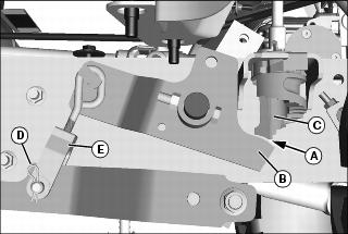
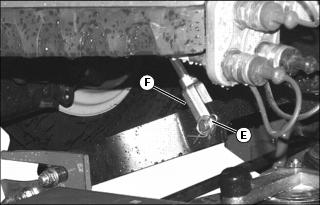
3. Check the gap (A) between the mower lift link (B) and height stop cam (C) on the machine. This measurement must be minimized to achieve maximum height-of-cut.
4. To adjust the height-of-cut linkage:
b. Remove the spring pin (D) and pivot pin securing both turnbuckles (E) to the lift arms (left side shown).
c. Shorten the turnbuckle assemblies an equal number of turns to reduce the gap or lengthen the turnbuckle assemblies equally to increase the gap.
d. Install the turnbuckles on the lift arms.
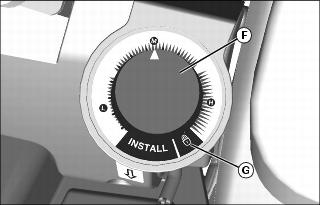
5. Raise the mower fully and rotate the Height-of-Cut control (F) to the lock position (G).
• If the control cannot be rotated to the lock position, the gap (A) was eliminated by shortening the turnbuckles excessively. Repeat the adjustment to slightly lengthen both turnbuckles equally until the Height-of-Cut control can be rotated to the lock position.
Adjusting Mower Wheels
1. Park machine on a level surface, not on a slope.
3. Raise mower, turn the height-of-cut control to the desired cutting height and lower mower.
5. Stop engine and remove key.
6. Wait for engine and all moving parts to stop before leaving operator’s seat.
a. Release gage wheel lock (A).
b. Adjust wheel assembly to 9.5 mm (3/8-in.) distance between gage wheels and ground.
IMPORTANT: Avoid damage! Ensure that at least one hole remains above lock bracket. In extreme mowing conditions, retract wheels completely to avoid damage. |
c. Install snap lock pin (B) in hole just above gage wheel bracket.
d. Repeat for remaining gage wheels.
Engaging Mower
1. Review instructions on using mid-PTO included in your machine operator’s manual.
2. Follow machine operator’s manual instructions to engage mid-PTO and mower.
Unplugging Mower
1. Park machine safely. Wait for all moving parts to stop before getting off to inspect machine.
2. Check under mower deck and discharge chute for debris.
3. Remove debris, and re-check for proper operation.
Transporting Mower on Machine
Raise mower to the highest position and turn the height-of-cut control to the lock position.
Transporting Machine on Trailer
NOTE: Use a heavy-duty trailer to transport your machine.
1. Drive or back machine onto trailer so hood or engine cover opens from rear of trailer.
2. Lower any implements to trailer deck.
6. Close the fuel shut-off valve.
7. Fasten machine to trailer with heavy-duty straps, chains, or cables. Both front and rear straps must be directed down and outward from machine. Trailer must have signs and lights as required by law.


