
Installing - Mower
Installing The Mower

1. Park the front of the Front Mower next to the rear of the mower. Push arms should be in the raised position. Lift the seat to the second position.
2. Turn the crank clockwise to lower the mower lift frame.
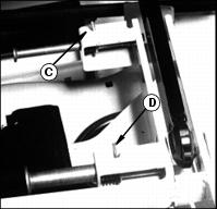
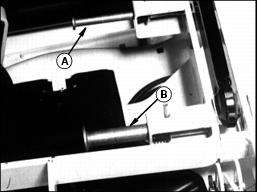
3. Pull out the spring pins (A and B) on each side until you can turn the latch rods (C and D) into the slots as shown.
4. Hold up the driveline and push the mower under the Front Mower. Lift the coupler and the driveline over the top of the transaxle.
NOTE: When you install the coupler on the vehicle gearbox shaft for the first time, you must first remove the plastic sleeve from the gearbox shaft.
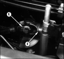
5. Install the coupler (E) on the vehicle gearbox drive shaft:
· Pull and hold the coupler sleeve (F) back.
· Push the coupler onto the shaft.
· Push and pull the coupler until you are sure it is locked on the shaft.
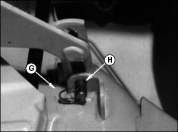
6. Remove the ring (G) and the drilled pin (H) from the rear of the mower on each side.
IMPORTANT: Avoid damage! Do not rotate the link (I) when you remove bracket (J) from the mower or install it on the shaft (K): You may change the mower level. |
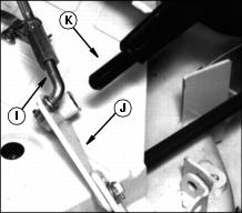
7. Lay each bracket off to the side as shown.
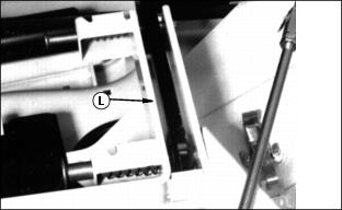
8. Push each arm (L) down into the lift frame.
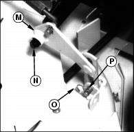
9. Install the bracket (M) on each side on the push arm shaft (N).
10. Install the drilled pin (O) and the ring (P) on each side.
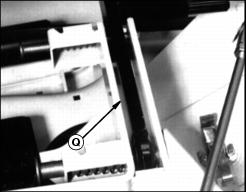
11. Each push arm (Q) should be down into the lift frame.
12. Turn the crank to line up the front frame holes with the front push arm holes.
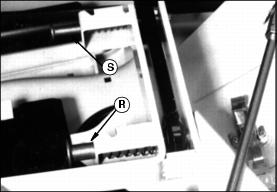
13. Turn the front spring pin (R) on each side to release its rod from the bracket slot. The pin should snap into the push arm hole.
14. Turn the crank counterclockwise to line up the rear frame holes with the rear push arm holes.
15. Turn the rear spring pin (S) on each side to release its rod from the bracket slot. The pin should snap into the push arm hole.
16. Adjust the cutting height and the rear mower wheel. See the Operating the Mower section.