Assembly
Remove Mower From Box
1. Cut and remove the tie strap from the driveline.
2. Remove and discard the screw holding the driveline. Remove the driveline from the box.
3. Remove and discard the screw from the right, rear of the mower.
4. Remove and discard the screw from the left front of the mower.
6. Remove the mower from the pallet.
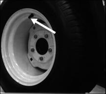
Install The Mower Wheel Right Side Up
The mower is shipped with the rear mower wheel upside down.
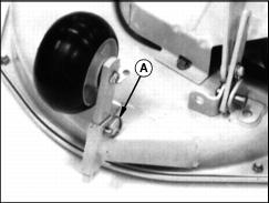
1. Remove the ring (A) and the drilled pin.
2. Remove the wheel and bracket.
3. Install the wheel right side up in the last position as shown.
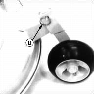
4. Install the drilled pin and the ring (B).
Install Mower Discharge Chute
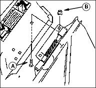
Install mower discharge chute to mower deck with two M8 x 16 bolts (A) and lock nuts (B).
Tighten nuts to 20 N·m (15 ft-lb).
Fasten The Driveline To The Mower Gearbox Shaft
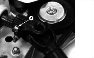
1. Line up the holes in the driveline coupler with the groove in the mower gearbox shaft.
2. Install the two M10 x 50 bolts (A) and lock nuts as shown-one from each side. Tighten the nuts to 75 N·m (55 lb-ft).
Remove Front Mower From Crate
1. Remove the two tie straps holding the ends of the push arms to the crate.
2. Remove and discard the lock nuts and flat washers from the two bolts holding the 2 x 4 to the rear bumper.
3. Remove and discard the two bolts from the rear bumper:
· Pry off and discard the tooth washer from each bolt.
· Remove and discard the rubber washer from each bolt.
· Remove and discard each bolt and flat washer.
4. Remove the bag containing the steering wheel, the operator's manual, and the bag of parts.
6. Remove and discard the two screws from the front 2 x 4.
7. Remove and discard the two brackets used to hold the front
2 x 4.
8. Remove and discard the two round-head bolts and lock nuts from each bracket.
Install The Seat
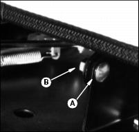
1. Fasten the seat to the base with two M8 x 20 round-head bolts (A), spacers, and flanged nuts (B).
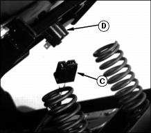
2. Connect the lead (C) to the seat safety switch (D).
Install The Steering Wheel
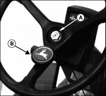
1. Put the rear wheels in the straight-ahead position.
2. Install the 65-mm (2-1/2-in.) black plastic spacer on the steering wheel shaft.
3. Put the steering wheel on the shaft with one spoke pointing to the rear.
4. Install and tighten the nut (A).
5. Push the cover with insert (B) onto the steering wheel with the leaping deer in the upright position.
Activate Battery
IMPORTANT: Avoid damage! To prevent damage to tractor from spilled electrolyte, remove the battery from the tractor. |
1. Remove the battery from the vehicle.
2. Remove and discard tape from across battery cells.
3. Remove and discard blue cell caps.
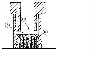
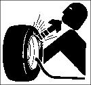
· Only use battery acid with a 1.265 specific gravity. Slowly add acid (A) to each cell. The solution should be 6 mm (1/4 in.) above plates (B), but NO HIGHER THAN 6 mm (1/4 in.) from the bottom of the filler neck (C).
5. Install the battery manifold cap from the bag of parts. Be sure manifold cap hose is behind positive cable.
6. Charge the battery for a MINIMUM of 30 minutes at 5-10 amps. If your battery charger has a Deep Cycle or Maintenance Free setting, use this setting to charge the battery. Failure to charge the battery before use will reduce battery performance and life.
NOTE: In the bag of parts there may be an extra 6M x 30 bolt and shoulder nut for the negative (-) cable clamp.
8. Install the battery cap drain hose through the hole in the battery base and through the hole in the side of the frame.
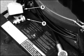
9. Connect red positive (+) cable (A) to battery. Apply petroleum jelly or silicone spray to terminal to prevent corrosion. Make sure connection is tight. Push red positive cover (B) over positive terminal.
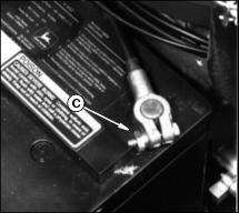
10. Connect black negative (-) cable (C) to battery. Apply petroleum jelly or silicone spray to terminal to prevent corrosion. Make sure connection is tight.