
Assembly - Thatcherator
Identify Parts

Box of Parts
Bag of Parts
Assemble Tow Bars
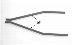
1. Align tow bars (A) as shown.
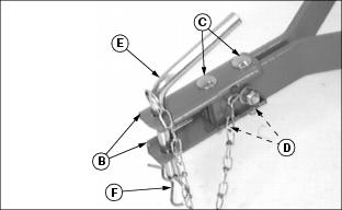
2. Assemble two clevis straps (B) to front of tow bars using two 5/16 x 2-1/4 in. carriage bolts (C) and two locknuts (D). Hand tighten only.
3. Slide clevis assembly forward until front carriage bolt is within 6 mm (1/4 in.) from the end of tow bars.
4. Install hitch pin (E) in clevis and fasten with spring locking pin (F) through chain loop.
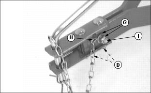
5. Install 5/16 x 1-1/2 in. cross hex bolt (I). Place chain hook (H) around bolt and secure with 5/16 in. flat washer and locknut (I).
6. Align tow bars and clevis. Tighten nuts (D) completely.
7. Tighten nylock nut (G) while holding chain hook forward and centered between clevis halves.
Install Tow Bars to Tray Assembly
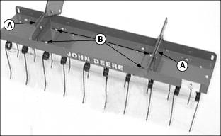
1. Using second set of holes on left side of tray and third set of holes on right side of tray, fasten two mounting brackets (A) to the tine tray with the small flange resting on the tray surface and facing inward. Secure with four 5/16 x 1 in. carriage bolts and hex nuts (B). Hand tighten only.
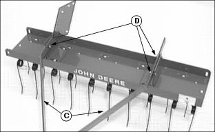
2. Attach tow bars (C) to the inside surfaces of the mounting brackets using three 5/16 x 1 in. carriage bolts and locknuts (D). Hand tighten only.
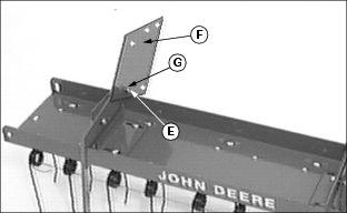
3. Align hole (E) in the lift lock plate (F) with holes in the right tow bar and mounting bracket. Attach the lift lock plate to the inside of the tow bar with a 5/16 x 1-1/4 in. carriage bolt and locknut (G). Hand tighten only.
Install Carriage Frame Assembly and Lift Handle
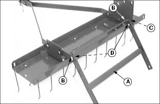
1. Attach carriage frame assembly (A) (side with two holes should be next to lift lock plate) to rear holes (B) in tow bars and lift lock plate at right side (C). Secure with 3/8 x 1-1/4 in. hex bolt (left side) and 3/8 x 1-1/2 in. (right side lift lock plate), 3/8 in. bushings, 3/8 in. flat washers, and fasten with 3/8 in. locknuts (D). Tighten so bar is secure but free to pivot.
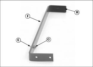
2. Pre-assemble lift lock pin (E) into hole in lift handle (F) with pin extending away from bend in lift handle. Secure with 5/16 in. lockwasher and 5/16 in. hex nut (G). Tighten securely.
3. Slide vinyl handle grip (H) over end of lift handle.
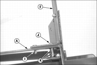
4. Attach the lift handle (F) to holes in top of carriage frame (A) using one 5/16 x 1-1/4 in. carriage bolt and locknut (I) and one 5/16 x 2 in. carriage bolt (J), spring, flat washer, and locknut (K).
5. Push the lift handle against lift lock plate and tighten bolts until locknuts have two bolt threads exposed.
Install Wheels
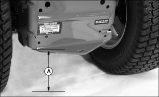
1. Measure length (A) from ground to top of hitch plate with tractor parked on a level surface.
NOTE: If length (A) is 22.9 cm (9 in.) or more, wheel is attached at top hole shown in wheel strap (B). Use lower hole if length is less.
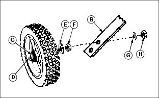
2. Install one 5/8 in. flat washer (C) onto 5/8 x 3 in. hex bolt (D).
3. Slide wheel onto bolt so side with flat hub surface (not rounded) is seated against washer and bolt head.
4. Install 5/8 in. flat washer (E) and 5/8 in. hex nut (F) onto threaded end of bolt. Tighten nut enough so the wheel can still spin freely.
5. Install wheel assembly to outside of wheel strap (B) using top or bottom hole as required. Secure with lockwasher (G) and 5/8 in. hex nut (H).