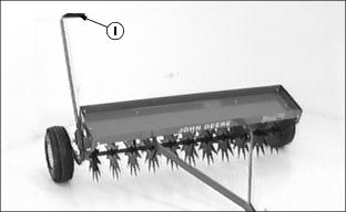
Assembly - Spiker Aerator
Identify Parts
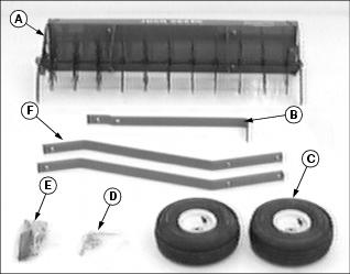
Box of Parts
Bag of Parts
Assemble Tow Bars
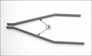
1. Align tow bars (A) as shown.
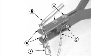
2. Assemble two clevis straps (B) to front of tow bars using two 5/16 x 2-1/4 in. carriage bolts (C) and two locknuts (D). Hand tighten only.
3. Slide clevis assembly forward until front carriage bolt is within 6 mm (1/4 in.) from the end of tow bars.
4. Install hitch pin (E) in clevis and fasten with spring locking pin (F) through chain loop.
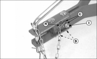
5. Install 5/16 x 1-1/2 in. cross hex bolt (I). Place chain hook (H) around bolt and secure with 5/16 in. flat washer and locknut (I).
6. Align tow bars and clevis. Tighten nuts (D) completely.
7. Tighten nylock nut (G) while holding chain hook forward and centered between clevis halves.
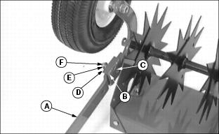
Install Tow Bars to Tray Assembly
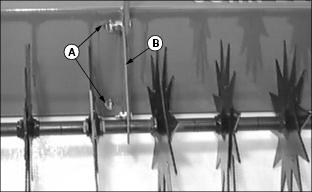
1. Stand tray assembly on its back. Loosen nylock nuts (A) on mounting brackets (B) to ensure proper bracket alignment while installing tow bars.
NOTE: You may want to have a helper or use a hoist to steady tow bars during alignment.
2. Align tow bars (C) to insides of brackets (B) and fasten with two 5/16 x 1 in. hex bolts (D), flat washer (E), and nylock nuts (F). Hand tighten only. Repeat for other side.
3. Hold tow bars all the way to top of slots and tighten nylock nuts (F).
4. Tighten nylock nuts (A) on mounting brackets.
Assemble Transport Wheels
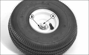
1. Install 1/2 x 3-3/4 in. hex bolt (A) and 1/2 in. flat washer (B) on valve stem side of wheel hub.
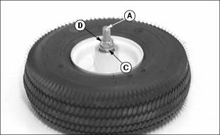
2. Turn wheel over to install second 1/2 in. flat washer (C) and 1/2 in. hex nut (D).
3. Tighten nut (D) until washers (B) and (C) keep bearing from turning on bolt without forcing bearings to be pressed inward. This causes wheel hub to rotate on bearings.
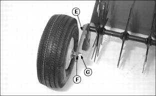
4. Install wheel assembly on lift arm (E), one on each side, and secure with 1/2 in. lockwasher (F) and 1/2 in. hex nut (G). Tighten nut securely so wheel hubs are free to turn on bearings.
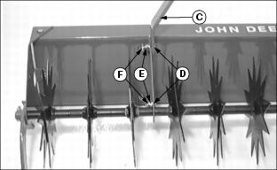
Install Lift Lever
1. Turn tray on its top and align lift lever (A), with offset to outside, to right side of lift arm (B).
2. Fasten with 3/8 x 2 in. flat-top beveled carriage bolt (C), head of bolt to the inside, and on outside spring (D), 3/8 in. flat washer (E), and 3/8 in. oblong locknut (F).
NOTE: Be sure head of carriage bolt (C) is properly seated in square hole of wheel assembly bracket during tightening of locknut.
3. Tighten locknut (F) until one full thread is exposed.
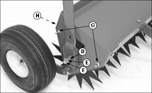
4. Turn tray upright and install two 5/16 in. transport lock pins (G), extending pin to the outside, and fasten with 5/16 in. lockwashers, and 5/16 in. hex nuts (H) to the inside. Tighten nuts.