
Assembly - Aerator-Spreader
Identify Parts

Box of Parts
Bag of Parts
Assemble Transport Wheels
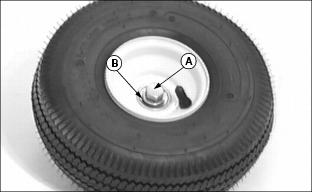
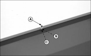
1. Install 1/2 x 3-3/4 in. hex bolt (A) and 1/2 in. flat washer (B) on valve stem side of wheel hub.

2. Turn wheel over to install second 1/2 in. flat washer (C) and 1/2 in. hex nut (D).
3. Tighten nut (D) until washers (B) and (C) keep bearing from turning on bolt without forcing bearings to be pressed inward. This causes wheel hub to rotate on bearings.
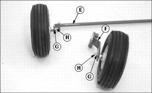
4. Install wheel assemblies to support brackets (E) and (F) and fasten with 1/2 in. lockwasher (G) and 1/2 in. hex nut (H).
5. Tighten nut securely so wheel hubs are free to turn on bearings.
6. Set wheel assemblies aside.
Assemble Tow Bars

1. Align tow bars (A) as shown.
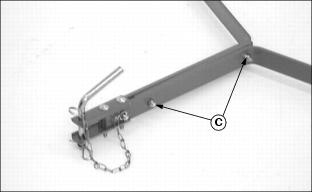
2. Align support strap (B) between tow bars and fasten with two 5/16 x 1-1/2 in. hex bolts and nylock nuts (C). Hand tighten only.
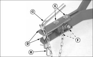
3. Assemble two clevis straps (D) to front of tow bars using two 5/16 x 2-1/4 in. carriage bolts (E) and two locknuts (F). Hand tighten only.
4. Slide clevis assembly forward until front carriage bolt is within 6 mm (1/4 in.) from the end of tow bars.
5. Install hitch pin (G) in clevis and fasten with spring locking pin (H) through chain loop.

6. Install 5/16 x 1-1/2 in. cross hex bolt (I). Place chain hook (J) around bolt and secure with 5/16 in. flat washer and locknut (K).
7. Align tow bars and clevis. Tighten nuts (F) completely.
8. Tighten nylock nut (K) while holding chain hook forward and centered between clevis halves.
9. Tighten tow bar nylock nuts (C).
Install Tow Bars, Wheel Assembly, and Lift Lever to Hopper
1. Align four tow bar holes with four hopper side holes.
2. Fasten tow bar to hopper with three 5/16 x 3/4 in. hex bolts, bolt heads to the inside, and nylock nuts (A). Hand tighten only.

3. Install three transport lock pins (B) into lift plate (C) as shown and fasten with three 5/16 in. lockwashers and hex nuts (D).
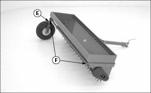
4. Install left wheel assembly (E) with long shaft through large holes (F) of tow bar.
5. Install lift plate assembly (C) onto end of long shaft.

6. Align small hole of lift plate with tow bar and hopper small holes.
7. Fasten with 5/16 x 1-1/4 in. hex bolt and nylock nut (G).
8. Hold tow bar so top edge of tow bar is parallel with top edge of hopper.
9. Tighten three nylock nuts (A) and last installed nylock nut (G).

10. Install 3/8 x 2 in. special bolt (H), head of bolt to the inside, into right wheel assembly bracket (I).
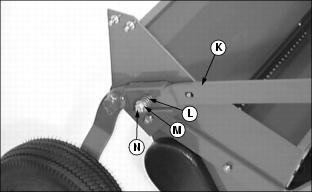
11. Install right wheel assembly (I) on to end of long shaft and fasten with 5/16 x 1-1/2 in. hex bolt and nylock nut (J).
12. Install lift lever (K), with offset to the outside, onto special bolt (H) and fasten with spring (L), 3/8 in. flat washer (M), and 3/8 in. locknut (N).
NOTE: Be sure head of special bolt (H) is properly seated in square hole of wheel assembly bracket during tightening of locknut.
13. Tighten locknut (N) until one full thread is exposed.

14. Slide vinyl handle grip (O) over end of lift lever.
Install Hopper Flow Control Lever
1. Stand hopper assembly on its back.
2. Remove 5/16 x 1-1/2 in. hex bolt, two large flat washers, and locknut (A) from hopper.

3. Install "L"-shaped end (B) of flow control lever into slot of calibration plate (C).
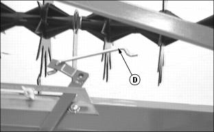
4. Install one end of shutter link (D) into end of flow control lever.
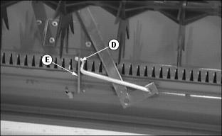
5. Slide lever down between hopper and spike assembly and install other end of shutter link (D) into shutter arm (E).

6. Slide lever up to align pivot hole with hopper hole and fasten with 5/16 x 1-1/2 in. hex bolt and large washer, (inside-out), and second large washer and locknut (A), (from the outside).
7. Tighten locknut until lever has sufficient drag to hold its position when released.
8. Return hopper assembly to the upright position.
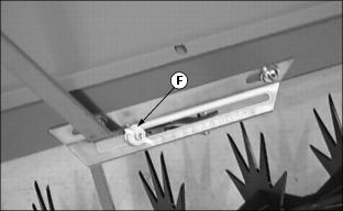
9. Move lever into closed position and lock it with wing nut lock assembly (F).
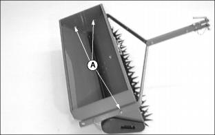
Install Weight Tray
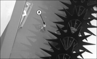
1. Install last transport lock pin (A) into center hole of rear hopper lip and fasten with 5/16 in. lockwasher (B) and hex nut (C).

2. Install weight tray (D) over pin (A) and hopper lips as shown.