
Operating
Tilling Tips
Install the correct front and rear tractor weights.
Check the tines before you till. Replace missing, bent, or broken tines.
When you till hard ground or sod, till at a shallow depth for the first pass. Till deeper on each pass after that.
When you till a small area, make a pass through the middle, then circle the original pass, working to the outside. After you finish, make a few passes around the edge to cover ridges left by turning.
Till straight ahead when possible. This will leave fewer ridges from turning.
For seed bed preparation, till the soil once in the fall. Decaying vegetation will add valuable nutrients to the soil by spring. If the terrain is hilly or uneven, wait until spring, or leave some untilled strips, to help reduce soil erosion. The climate and terrain will help you decide the best time to till.
Before Tilling
Test the soil by squeezing it in your hand. If the soil forms a ball, it is too wet to till. If soil does not compress easily or falls apart, it is ready to till.
Do not till when soil is wet. Wet soil will stick to the tines and tine shaft. Wet soil will also dry out and become hard, making it hard to work with during the growing season.
Mow tall weeds and grass to keep them from wrapping on tines or the tine shaft.
Pick up rocks, branches, and other objects that might damage the tiller.
Check the tines before tilling. Repair or replace loose, bent, or broken tines.
Raising and Lowering Tiller (Models 240, 245, 260, 265, 285, GT225, GT235, GT242, GT262, and GT275)
To Raise Tiller for Transport
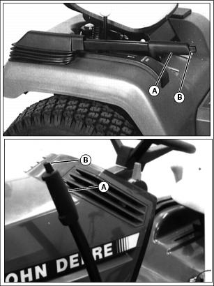
Picture Note: Upper Photo - 200 Series; Lower Photo - GT series
1. Push lift lever (A) down or forward (GT series) slightly.
3. Pull lever up or back (GT series) until it latches and tiller stays up.
To Lower Tiller to Lockout Position:
1. Pull lift lever (A) up or back (GT series) slightly.
3. Push lever down or forward (GT series) until it latches.
Raising and Lowering Tiller (Models 320, 325, 335, 345 and 355)
Push hydraulic lift lever (A) forward to lower tiller.
Picture Note: 325, 335, 345 and 355 Tractor
Pull hydraulic lift lever (A) rearward to raise tiller.
Raising and Lowering Tiller (Models with Foot Lift)
NOTE: Make sure the tension on the lift assist spring is properly adjusted to support the weight of the attachment installed.
Raising Tiller:
1. Push down and hold lift pedal (A).
2. Pull up lever (B) to lock tiller in the transport position.
3. Release lift pedal. Pedal should stay down and lever should stay locked.
Lowering Tiller:

1. Push down and hold lift pedal (A).
2. Push down lever (B) to unlock.
3. Release lift pedal to lower tiller.
Transport Position
Holds tiller above ground while traveling to and from worksite.
1. Push forward on lift pedal (A).
2. Raise pedal latch handle (B) to latch tiller in transport (raised) position.
3. Remove foot from lift pedal and the tiller stays up.
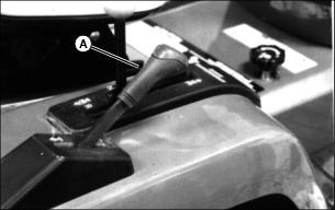
Tips for Adjusting Lift Spring (Models 240, 245, 260, 265, and 285)
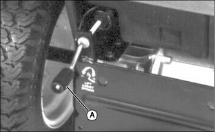
Before you adjust lift spring with crank (A), consider two points:
1. The effort required to lift the tiller in relation to the effort required to lock-out the lift spring:
• Too little spring tension may require too much effort to lift the tiller.
• Too much spring tension may require too much effort to push down and lock the lift lever down.
2. Field conditions and tiller performance:
• For difficult conditions you may need little or no spring tension, so the weight of the tiller holds it down in heavy soils or sod.
• For normal conditions you may need moderate spring tension, so the tiller performs well in light to medium soils and soil already tilled.
Adjusting Lift Spring (Models 240, 245, 260, 265, and 285)
NOTE: Adjust spring tension as necessary when operating the tiller:
• Heavy soils, clay, or sod require less spring tension.
• Light to medium soils, or soils already tilled, require more spring tension.
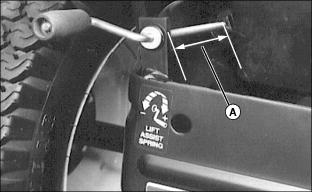
1. Turn crank until distance (A) is approximately 120 mm (4-3/4 in.).
2. Raise tiller all the way with lift lever, but do not release lever button.
• The tiller should drop to the ground by itself and
• The tiller should be raised with little effort. If not, adjust spring tension as desired. To increase spring tension, turn the crank clockwise. To decrease spring tension, turn the crank counter-clockwise.
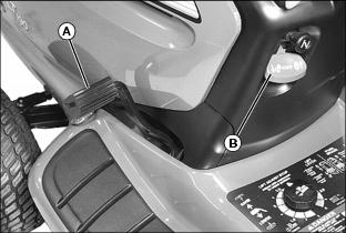
Adjusting Lift Assist Spring (Models with Foot Lift)
NOTE: Weight of attachment affects ease of lifting. Adjust lift assist spring for your particular attachment model.
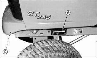
1. Make sure yellow indicator (A) is aligned with proper mark for attachment installed. If not, adjust lift assist spring so indicator is aligned with correct mark.
2. Turn adjusting bolt (B) at front of machine frame to adjust lift assist spring:
• Clockwise - Increases spring tension and moves indicator toward front of machine for heavier attachments.
• Counterclockwise - Decreases spring tension and moves indicator toward rear of machine for lighter attachments.
3. Field conditions and tiller performance:
• For difficult conditions you may need little or no spring tension, so the weight of the tiller holds it down in heavy soils or sod.
• For normal conditions you may need moderate spring tension, so the tiller performs well in light to medium soils and soil already tilled.
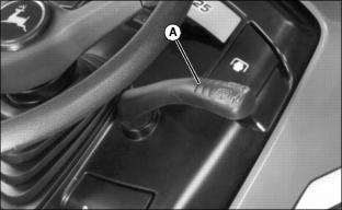
Using Depth Control Knob
Adjust this knob to set tilling depth. The tiller will return to the same depth each time you lower it.
1. Raise tiller as high as it will go.
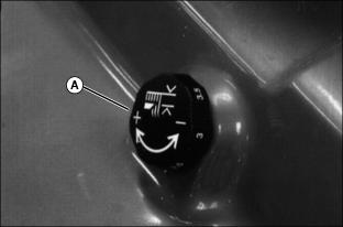
Picture Note: GT242, GT262 and GT275 Tractors Shown
2. Turn knob (A) clockwise to raise the tiller depth or counter-clockwise to lower the depth.
NOTE: If you cannot adjust for the desired tilling depth, see Adjusting Tilling Depth in Service section.
Adjusting Tilling Depth (Models 240, 245, 260, 265, 285, 320, 325, 335, 345 and 355)
1. Release the lift spring tension:
• Models 320, 325, 335, 345 and 355 – Push lift lever forward. Lower tiller to the ground.
• 200 Series Tractors – Turn crank at rear of tractor counter-clockwise.
NOTE: Tiller frame has been removed from tractor for clarity.
2. Remove spring locking pin (A).
3. Remove rod (B) from the plate.
IMPORTANT: Avoid damage! Do not expose more than 30 mm (1-1/4 in.) of thread (C) or lift rod could separate from clevis. |
NOTE: Maximum tilling depth is 150 mm (6 in.).
• To increase tilling depth, turn rod (B) out of clevis (D).
• To decrease tilling depth, turn rod (B) into clevis (D).
5. Install rod in plate and secure with spring locking pin.
6. Check tiller ground clearance:
• Use lift lever to raise tiller as high as it will go.
• Measure distance between ground and the lowest tine. The distance should be 75 mm (3 in.).
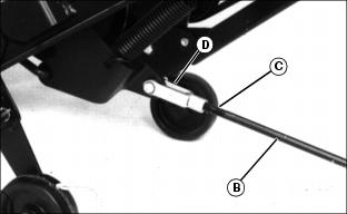
Adjusting Tilling Depth (Models GT225, GT235, GT242, GT262, and GT275)
1. Push manual lift lever forward to the lock-out position.
IMPORTANT: Avoid damage! Do not expose more than 30 mm (1-1/4 in.) of thread or lift rod could separate from clevis. |
Picture Note: Tiller frame removed from tractor for clarity.
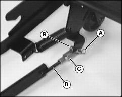
2. Remove cotter pin (A) and drilled pin (B) to disconnect clevis (C) from tiller frame.
NOTE: Maximum tilling depth is 150 mm (6 in.).
• To increase tilling depth, turn lift rod (D) out of clevis (C).
• To decrease tilling depth, turn lift rod (D) into clevis (C).
4. Install clevis (C) to tiller frame and fasten with drilled pin (B) and cotter pin (A).
5. Check tiller ground clearance:
• Use lift lever to raise tiller as high as it will go.
• Measure distance between ground and the lowest tine.
• The distance should be 75 mm (3 in.).
Operating Tiller
• Pick up objects from tilling area. • Guards and shields must be in place. • Clear the work area of people. |
1. Lock wheels (A) in the raised position.
2. Put tiller in the operating position:
• Raise tiller slightly with handle (B).
• Pull lever (C) out of the frame.
• Slowly lower tiller. Release lever (C). Make sure lever locks in place.
IMPORTANT: Avoid damage! To help prevent clutch damage, do not engage tiller with throttle lever in the fast position. |
3. Start engine. Put throttle lever at 1/4 position.
NOTE: For those tractors with RIO (Reverse Implement Option), the tiller will stop when the tractor is put in reverse.
4. To engage tiller, put PTO control in the on position.
5. Push throttle lever to the fast position.
7. Till ground at a safe travel speed.
Inspecting, Unplugging, or Parking Tiller
2. Put PTO control in the off position.
3. Lower tiller to the ground.
Transporting Tiller
Drive the tractor with the tiller in the transport position when traveling from one tilling area to the other. Drive the tractor at a safe travel speed. Slow down on slopes or rough ground.
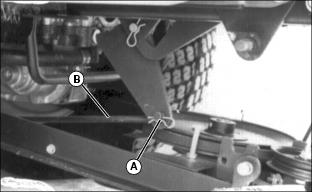
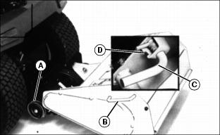
Place tiller in transport position as follows:
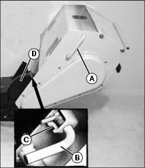
1. Grasp handle (A) and pull slightly upward on tiller to relieve tension on transport lever (B). Pull out and rotate the transport lever to engage locking pin in slot (C).
2. Pivot tiller up and forward as far as it will go.
3. Rotate transport lever (B) until locking pin disengages from slot (C). Allow transport lever to lock into hole in shield (D).