
Assembly
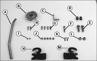
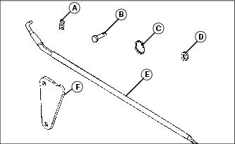
Identify Parts - Bag of Parts
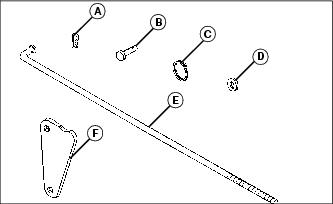
Identify Parts – Lift Assist Parts (Models 240, 245, 260, 265, 285 and 320)
NOTE: Parts ordered separately.
Identify Parts – Lift Assist Kit (Models GT242, GT262, and GT275)
Identify Parts – Lift Assist Kit (Models GT225 and GT235)
Identify Parts – Lift Assist Kit (Models 325, 335, 345 and 355)
Preparing the Vehicle
Remove Mower Deck
The mower deck must be removed from your tractor before installing the tiller. See your tractor operator’s manual or mower deck manual for removal instructions.
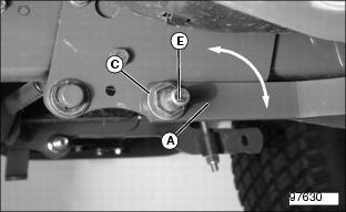
Install Rear Frame Mounting Hardware
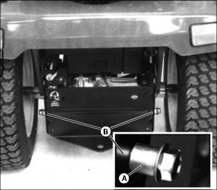
1. Install one spacer (A) over threaded end of each M12x50 flange bolt (B).
NOTE: If tractor frame has three holes on each side, use the lower front hole (C). If frame has two holes per side, use the bottom hole.
Picture Note: Right-hand side shown.
2. Install bolt (B) in proper hole on each side of tractor frame and secure with M12 locknut. Tighten locknut to 105 N•m (78 ft-lb).
Install Mounting Pins (Models GT225, GT235, GT242, GT262, and GT275)
NOTE: Complete the following steps on both sides of tractor.
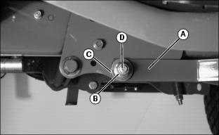
1. Locate draft arm (A) under tractor foot rest. Remove locknut (B), washer (C), and pivot bolt (D). Discard the pivot bolt.
2. Place draft arm (A) in its original position. Make sure spacer is in place.
NOTE: Some tractors may have two washers (C). If so, install both.
3. Install original washer (C) and special threaded pin (E) from kit. Secure with original locknut (B) at back side of draft arm. Tighten locknut completely.
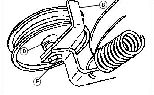
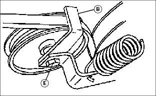
Install Clips On Tiller Frame
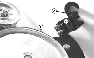
Picture Note: Right-hand clip shown
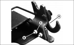
Picture Note: Left-hand clip shown
Attach tiller clip (A) to correct side of tiller frame with two M8x25 hex bolts (B) and M8 locknuts (C). Tighten locknuts to 20 N•m (15 ft-lb).
Install Idler Sheave
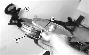
1. Position idler sheave (A) and belt guide (B) onto tensioning arm (C). Make sure shoulder (D) on sheave is seated against the belt guide.
2. Install M8x50 flange bolt (E) from bottom side of idler sheave. Install M8 locknut at top side of sheave. Do not tighten completely.
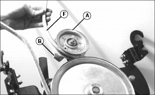
3. Route belt (F) between belt guide (B) and idler sheave (A).
4. Adjust the position of belt guide (B) as shown. Make sure belt guide does not contact idler sheave.
NOTE: Make sure belt guide does not move out of position when tightening locknut.
5. Hold bolt head (E) with wrench and tighten M8 locknut completely at top side of idler sheave.
6. After tightening, make sure the idler sheave rotates freely on the tensioning arm.
7. Pull the belt tight and make sure belt guide does not contact idler sheave or belt.
Install Attaching Assist Lever
1. Position attaching assist lever (A) on bottom surface of left side tiller frame. Install two M6x30 hex bolts (B). Make sure bent end (D) of lever faces outside.
2. Secure the assist lever with two M6 flange nuts (C). Tighten the nuts to 12 N•m (9 ft-lb).
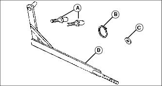
Fasten Plate to Lift Rod (Models 240, 245, 260, 265, 285, 320, 325 and 345)
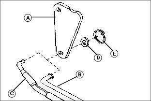
1. Position front lift link plate (A) as shown.
2. Place lift rod through lower hole in plate:
• Lift rod (B) – models 240, 245, 260, 265, 285, and 320.
• Lift rod (C) – models 325 and 345.
3. Install M13 washer (D) and secure with locking ring (E).
Fasten Arm to Lift Rod (Models with Foot Lift)
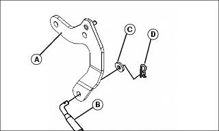
2. Place lift rod (B) through lower hole in arm.
3. Install M13 Washer (C) and secure with locking ring (D).
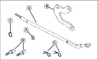
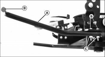
Install Lift Rod
NOTE: Straight lift rod shown. Lift rod may look different for your tractor model.
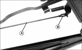
Tighten the threaded end of lift rod (A) into clevis (B) on tiller. Tighten the rod far enough so the threaded end is flush with the inside clevis hole but not passing through it.