
Operating
Operate Safely
· View the videotape provided with the vehicle for safe operating practices.
· DO NOT misuse the ProGator® Utility Vehicle, it is a utility vehicle NOT a recreation vehicle.
· Sit on the center of the seat and keep both feet within the foot platform perimeter. Clean foot platform if dirty, and remove any debris from around foot controls.
· Check for debris or refuse in the battery storage compartment, especially around brake linkage which attaches to axle housing on each side of the transaxle.
· Always use both hands for steering.
· Know location of controls and how and what they operate.
· Never operate utility vehicle while standing.
· Never operate utility vehicle with the cargo box or any attachment raised.
· Check brake action before beginning vehicle operation. Adjust or service the brakes as necessary.
· To provide adequate braking ability and traction, DO NOT tow any attachment or loaded trailer unless the utility vehicle cargo box is loaded.
· Inspect vehicle before operating. Be sure hardware is tight. Repair or replace damaged, badly worn, or missing parts. Be sure guards and shields are in good condition and fastened in place. Make any necessary adjustments before operating.
· Keep people and pets out of the work area. Stop the vehicle if anyone enters the area. If an object is hit, stop and inspect the vehicle for damage. Make repairs before operating. Keep the vehicle properly maintained and in good working order.
· Keep headlight and taillight lenses clean.
· DO NOT leave vehicle unattended when it is running.
· Only operate during daylight or with good artificial light.
· Be careful of traffic when operating near or crossing roadways.
· This vehicle is NOT intended for use on highways or public roadways. It is to be used for off-road use only.
· Avoid sudden starts, stops, or turns.
· Always use a level turn-around area.
· DO NOT wear radio or music headphones while operating the vehicle. Safe operation requires your full attention.
Park Safely
· Stop the vehicle on a level surface, not on a slope.
· Place transmission in first or reverse gear.
· Before leaving the operator's seat, wait for the engine and all moving parts to STOP.
· Block wheels if it is necessary to park the vehicle on an incline.
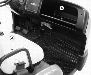
Use Hand Holds
Hand Holds (A) are provided for operator and passenger balance when driving over rough terrain. Use dash bar and side rails on seats for stability.
Use Seat Belt Properly
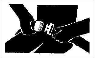
Use a seat belt when you operate with a Roll-Over Protective Structure (ROPS) or cab to minimize the chance of injury from an accident, such as an overturn.
Protect Children and Prevent Accidents
· Never assume that children will remain where you last saw them. Stay alert to the presence of children.
· If the vehicle is equipped with a cargo box, never carry children in the cargo box area. DO NOT allow children to ride in a utility vehicle cargo box or on any attachment. DO NOT tow children in a cart or trailer.
· Use extra care when coming to blind corners, shrubs, trees, or other objects that may block vision.
· DO NOT let children or an untrained person operate the vehicle.
· Before backing or turning, look behind and around the utility vehicle for children.
· Be alert at all times, drive forward and in reverse carefully. People, especially children, can move quickly into an area of operation.
· Back carefully. Look behind the vehicle, especially for children, before backing up.
· DO NOT operate vehicle if under the influence of alcohol or other drugs.
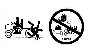
· Misuse and recreational riding can lead to accidents, severe bodily injury or death.
Avoid Tipping
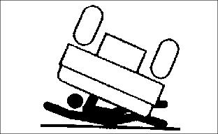
Accidents resulting in serious injury or death can occur from tipping the utility vehicle. Observe the following practices to help prevent accidents:
· DO NOT misuse this utility vehicle. This utility vehicle is not designed for recreational riding.
· Never allow riders in the cargo box or other areas where seats are not provided.
· Drive very slowly when turning. Sharp turns could cause the utility vehicle to tip over.
· Reduce speed and exercise extreme caution on slopes or on rough ground.
· DO NOT overload vehicle and avoid shifting loads. Reduce load when operating over rough or hilly terrain.
· Stay alert for holes, rocks, loose terrain, wet or slippery surfaces and other hidden hazards in the terrain.
· DO NOT stop or start suddenly when going uphill or downhill. Be especially cautious when changing direction on slopes.
· Keep front wheels straight at crest of hill or going over bumps.
· When descending a hill, remove foot from accelerator and apply brakes to reduce speed and maintain control.
· DO NOT make changes or modifications to this utility vehicle.
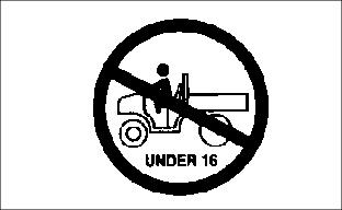
Operator Training Required
Study Operating section of this manual before operating the vehicle.
· Operate vehicle in an open, unobstructed area under the direction of an experienced operator.
· Learn the use of all controls.
· Operator experience is required to learn the moving, stopping, turning and other operating characteristics of the vehicle.
· Young drivers may not have the strength or experience to control the utility vehicle. This increases the chances of rolling the vehicle over resulting in severe bodily injury or death.
· The utility vehicle should NOT be operated by anyone under the age of 16 years.
Stay Clear Of Rotating Drivelines
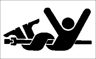
Entanglement in rotating driveline can cause serious injury or death:
· Keep hands, feet, and clothing away from power driven parts.
· Wear close fitting clothing.
· STOP the engine and be sure PTO driveline is stopped before getting near it.
Keep Riders Off Vehicle
· Seating is provided for operator and one passenger. No riders are allowed in cargo box or anywhere else on vehicle.
· Riders on vehicle are subject to injury such as being struck by foreign objects or being thrown off of the vehicle and severely injured or killed.
· Riders affect the operators ability to control the vehicle as well as its center of gravity. Also, riders could obstruct the operator's view resulting in the vehicle being operated in an unsafe manner.
Wear Appropriate Clothing
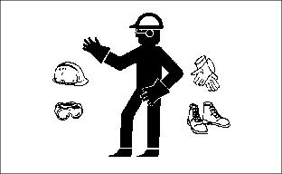
· Wear close fitting clothing and safety equipment appropriate for the job.
· Loud noise can cause impairment or loss of hearing, wear a suitable protective device such as earplugs.
· Do not wear radio or music headphones while operating the vehicle. Safe operation requires your full attention.
Avoid High Pressure Fluids
· Hydraulic hoses can fail due to physical damage, kinks, age, and exposure. Check hoses regularly. Replace damaged hoses.
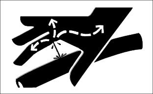
· Escaping fluid under pressure can penetrate the skin causing serious injury. Avoid the hazard by relieving pressure before disconnecting hydraulic or other lines. Tighten all connections before applying pressure.
· Search for leaks with a piece of cardboard. Protect hands and body from high pressure fluids.
· If an accident occurs, see a doctor immediately. Any fluid injected into the skin must be surgically removed within a few hours or gangrene may result. Doctors unfamiliar with this type of injury should reference a knowledgeable medical source. Such information is available from Deere & Company Medical Department in Moline, Illinois, U.S.A. Information may be obtained in the United States and Canada only by calling
1-800-822-8262.
Transport Safely
· Use safety lights and devices. Slow moving vehicles when driven on public roads are hard to see, especially at night. Avoid personal injury or death resulting from a collision with a vehicle.
· Flashing warning lights are recommended whenever driving on public roads to increase visibility. Extra flashing warning lights may need to be installed.
· A safety lighting kit is available from your John Deere distributor.
Attachments
· Use approved attachments only.
· Traction is reduced without an attachment installed. Operate only on level ground and slowly without an attachment.
Check Wheel Hardware
· A serious accident could occur causing serious injury if wheel hardware is not tight.
· Check wheel hardware tightness often during the first 100 hours of operation.
Adjusting Vehicle Seats
1. Sit on the operator or passenger seat.
2. Pull and hold lever (A) to the left.
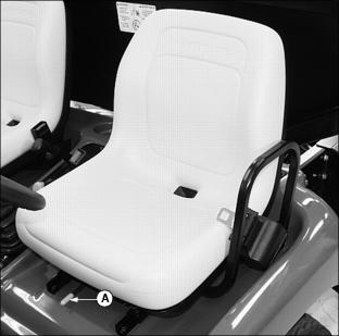
Picture Note: Operator seat shown.
3. Slide seat forward or rearward to desired position.
Using Seat Belts
· With one continuous motion pull seat belt from retractor (A) and across hips and waist.
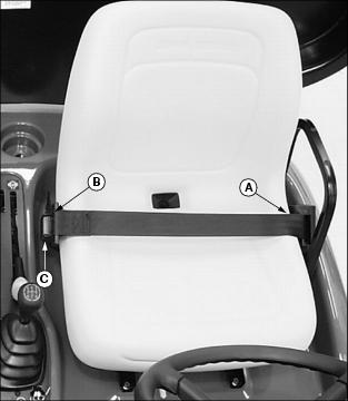
NOTE: If seat belt stops short of being able to insert into latch, allow belt to return into the retractor and pull again.
· Insert buckle into latch (B) on other side of seat. When properly inserted into the latch a "click" should be heard.
· Press red button (C). Allow seat belt to return to retractor.
Using Fuel Shut-Off Valve (Diesel Models)
1. Locate fuel filter sediment bowl assembly on the left side of the engine.
2. Rotate two-position fuel shut-off valve lever (A) to the "O" (open) position or "C" (closed) position.
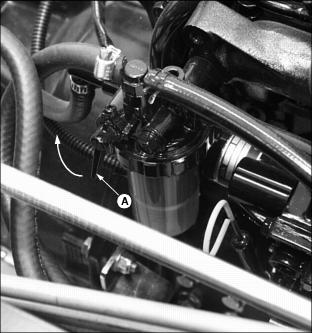
Picture Note: Fuel shut-off valve shown in the open position.
"C" (Closed) position:
· When performing any type of engine service.
· During periods of extended storage.
"O" (Open) position:
· Fuel shut-off valve must be in the full OPEN position for proper fuel delivery to the engine.
Using the Park Brake
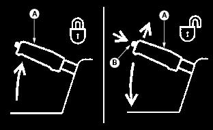
· Pull up lever (A) and latch into position.
· Push lever (A) down completely. Instrument panel indicator light must go out.
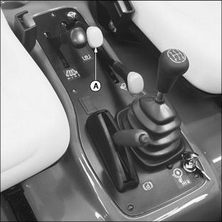
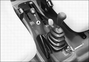
Using the Differential Lock Lever
The differential lock is used to provide better traction when the rear wheels of the vehicle start to slip. Engaging the differential lock lever will lock the left and right rear axles together and cause both rear wheels to turn at equal speeds for maximum traction.
IMPORTANT: Avoid damage! To prevent damage to the transmission, DO NOT engage differential lock when the vehicle is traveling at high speeds. |
NOTE: Vehicle turning radius is increased when the differential lock is engaged.
· Pull up and hold differential lock lever (A) in the raised position. Hold lever in the raised position as long as there is rear wheel slippage.
To DISENGAGE differential lock:
· Lower differential lock lever (A).
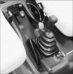
Using the Hydraulic PTO Control Lever
Perform this operational procedure with vehicles equipped with the auxiliary hydraulic kit. Engaging the hydraulic PTO lever will provide auxiliary hydraulics for attachments requiring the capability.
· Pull up lever (A) to the ON (P) position.
To DISENGAGE the hydraulic PTO:
· Push lever (A) down to the OFF (p) position.
Using the Lift Cylinder Lever
To RAISE attachment:
2. Pull and hold back lever (A).
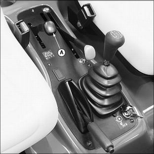
3. Release lever. Lever will return to the neutral position, and attachment will be held in position with the lift cylinder locked in place.
To LOWER attachment:
NOTE: An attachment can be lowered and the lift cylinder will retract with the engine running or the engine stopped.
1. Push and hold down lever until attachment is lowered or positioned as desired.
2. Release lever. Lever will return to the neutral position, and attachment will be held in position, with the lift cylinder locked in place.
NOTE: When operating the vehicle with the auxiliary hydraulic PTO engaged, it is recommended that the lift cylinder lever be held down momentarily after the attachment has been lowered. This will firmly seat the load check for the lift cylinder spool which locks the lift cylinder in position.
When operating the vehicle with a cargo box attachment having the tailgate release kit installed, the lift cylinder lever must be held down momentarily after the box has been lowered. This will lock the tailgate and eliminate tailgate rattle.
To allow attachment to FLOAT:
NOTE: Float position allows the lift cylinder to move freely for use with some ground following attachments.
Placing the lift cylinder lever in the float position will cause a raised attachment to be lowered by gravity until completely down. For best control of raised loads, it is recommended that float position NOT be used to lower attachments.
1. Push lever (A) in, then down for float position.
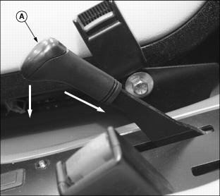
2. Pull up lever to release float position.
3. Release lever. Lever will return to the neutral position, and attachment will be held in position, with the lift cylinder locked in place.
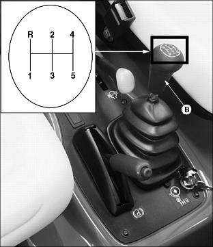
Using the 5th Gear Lockout
This vehicle is equipped with a keyed lock (A) for 5th gear lockout. Preventing the use of 5th gear while limiting vehicle ground speed may be advisable in certain operating conditions.
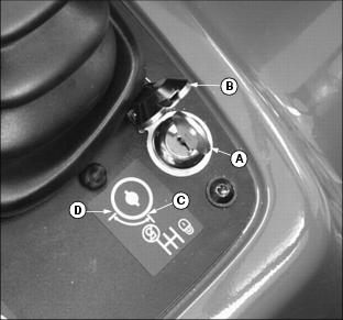
Picture Note: Key position shown with 5th gear locked out.
NOTE: Lock will not operate if vehicle transmission is already in 5th gear.
1. Move gear shift lever to any position except 5th gear.
3. Install key into key switch.
IMPORTANT: Avoid damage! DO NOT operate the vehicle with the key left in the lock. The switch cover must be allowed to close to prevent water, sand and other contaminants from entering the lock. |
1. Move gear shift lever to any position.
3. Install key into key switch.
Instrument Panel
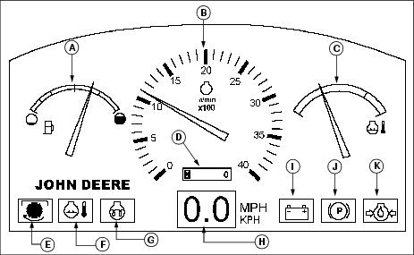
F - Coolant Temperature Indicator
G - Glow Plug Circuit Indicator
(Diesel Model)
I - Battery Low Voltage Indicator
K - Engine Oil Pressure Indicator
Operating the 5-Speed Synchronized Transmission
Using the Clutch Pedal
The functions of the clutch pedal (A) are:
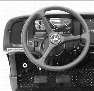
· Connects and disconnects engine power to the transmission.
· Operates in conjunction with the gear shift lever to shift gears.
· Press the clutch pedal down completely. This will disengage the transmission from engine power.
· Remove foot from clutch pedal slowly. This will engage the transmission to engine power.
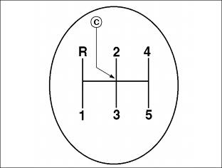
Using the Gear Shift Lever
The gear shift lever (B) is located on a console to the right of the operator seat. The gear shift lever provides five forward travel speeds and one reverse speed.
Select a gear on the gear shift lever that matches desired speed and direction. First and second gears are very low and should be used when hauling heavy loads.
Forward Travel
NOTE: The gear shift lever must be in the NEUTRAL position for the engine to start.
2. Move the gear shift lever to the NEUTRAL position (C) between gears "2" and "3".
3. Depress clutch pedal and start engine.
4. Move gear shift lever to a desirable starting gear.
· Vehicles with a load-first gear
· Vehicles with no load-second or third gear
6. Release clutch gradually to take up load smoothly.
· Depress clutch and shift to next gear.
Reverse Travel
3. Move gear shift lever to REVERSE.
Starting the Engine
3. Push hydraulic PTO lever to the OFF (p) position.
4. Move the gear shift lever to the NEUTRAL position.
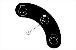
5. Turn key switch to the RUN position (A).
· Battery discharge indicator light should be on.
· Park brake indicator light should be on.
· Engine oil pressure indicator light should be on.
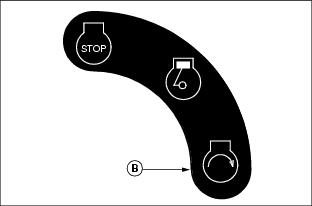
7. Turn key switch to the START position (B).
NOTE: Engine is calibrated at the factory to slow idle at 1450 RPM
8. When engine starts, release key switch to the RUN position.
· Battery discharge indicator light should go out.
· Engine oil pressure indicator light should go out.
· Park brake indicator light should go out.
Stopping the Engine
1. Release accelerator pedal and allow engine to slow idle.
2. Depress the clutch pedal and the foot brake.
3. Place gear shift lever in first or reverse gear.
5. Turn key switch to the "STOP" position (A).

Daily Operating Checklist
o Test Safety Interlock System
Testing Safety Interlock System
Use the following checkout procedure to check for normal operation of the utility vehicle.
If there is a malfunction during one of these procedures, DO NOT operate the utility vehicle. (See your John Deere dealer for service.)
Perform these tests in a clear open area with the vehicle parked on a hard, level surface. Keep bystanders away.
Testing Seat and Park Brake Switches
3. Move gear shift lever to the NEUTRAL position.
5. With engine running at slow idle, raise off seat.
6. Engine must continue to run.
10. Engine must stop within five seconds. If the engine does not stop, there is a problem with the safety interlock circuit. (See your John Deere Dealer.)
Testing Neutral Switch
3. Move the gear shift lever to the "R" (REVERSE) position.
4. Turn the key switch to the START position.
6. Repeat starting procedure with shift lever in each gear.
8. Move the gear shift lever to the NEUTRAL position.
9. Turn the key switch to the START position.
10. Engine should crank. If the engine should start with the gear shift lever in any position other than the NEUTRAL position, there is a problem with the safety interlock circuit. (See your John Deere Dealer.)
Testing Auxiliary Hydraulic System Switch
NOTE: Make sure no attachments are connected to the auxiliary hydraulic quick-couplers at the rear of the vehicle.
3. Move the gear shift lever to the NEUTRAL position.
4. Pull up hydraulic PTO lever to the ON (P) position.
5. Turn the key switch to the START position.
6. Engine must not crank. If the engine should start, there is a problem with the safety interlock circuit. (See your John Deere Dealer.)
Operating Vehicle Engine with Operator Off the Seat
NOTE: During normal operating conditions, the vehicle engine should stop running when the operator raises off the seat.
To keep engine running when operator is off the seat:
1. Depress clutch and foot brake pedals to stop the vehicle.
2. Move the gear shift lever to the NEUTRAL position.
4. Slowly release clutch and foot brake pedals.
· Engine should continue to run with the operator off of the seat.
Towing the Utility Vehicle
1. Move gear shift lever to the NEUTRAL position.
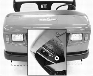
2. Attach a tow line to oval slot (A) provided on either side of the main frame under the front of the vehicle.
4. Tow vehicle slowly and carefully to desired location.
Towing Loads
· DO NOT tow a load with this vehicle that exceeds 680 kg (1500 lb).
· DO NOT exceed a tongue weight of 90.7 kg (200 lb).
· Tow load at a speed slow enough to maintain control.
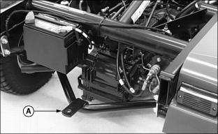
· Always use rear hitch point (A) provided on and approved for this utility vehicle. This is an approved hitch point, DO NOT modify in any way.
Transporting Utility Vehicle
1. Drive vehicle forward onto a trailer.
2. Park vehicle safely. (See Park Safely in this section.)
4. Block rear wheels with chocks or wood blocks.
5. Fasten vehicle to trailer with heavy-duty straps, chains, or cables.
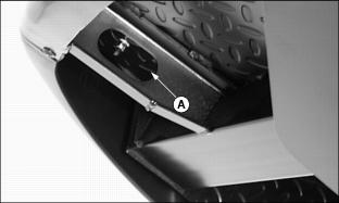
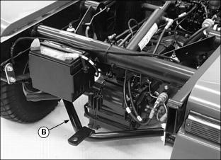
· The tie downs should be attached to oval slots (A) provided on both sides of the main frame under the front of the vehicle and both sides of the hitch assembly (B) at the rear of the vehicle.
· Both front and rear straps must be directed down and outward from the vehicle.
6. When transporting the utility vehicle on a road or highway, use accessory lights and devices for adequate warning to operators of other vehicles. Check local, state, provincial, or federal laws.
Raising and Lowering the Cargo Box
2. Pull and hold back lift cylinder lever (A) to raise cargo box.
NOTE: The lift cylinder will retract and the cargo box will lower with the engine running or the engine stopped.
3. Push and hold down lever (A) to lower cargo box.
Operating the Cargo Box Tailgate
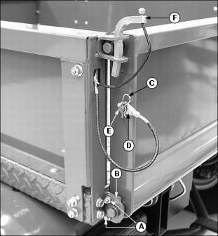
1. Pull up and remove each tailgate latch pin (A).
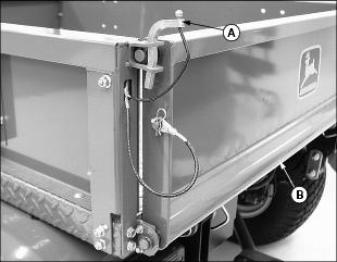
IMPORTANT: Avoid damage! Avoid the possibility of the tailgate making contact with the rear fenders causing structural damage. DO NOT operate utility vehicle with the tailgate fully lowered. |
3. Remove spring locking pin (C) and cable (D) from each drilled stud (E) to fully lower tailgate.
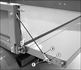
Removing the Cargo Box Tailgate
1. Close the tailgate and latch both sides.
2. Remove two screws (A) and tailgate support plates (B) from each side.
3. Remove spring locking pin (C) and cable (D) from each drilled stud (E).