
Assembly
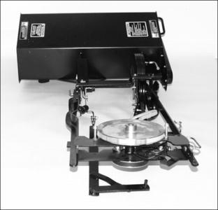
Identify Parts - 30 Inch Mechanical Tiller
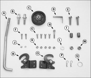
Bag of Parts
Install Tractor Rear-Frame Hardware
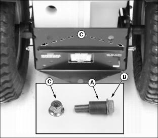
1. From bag of parts, install one spacer (A) on each M12 x 1.75 x 50 mm flange bolt (B).
2. Install spacers and bolts in BOTTOM holes at rear of tractor frame and secure with M12 x 1.75 locknuts (C) on inside of tractor frame. Tighten locknuts to 105 N·m (78 ft-lb).
Install Tractor Mid-Frame Mounting Pins
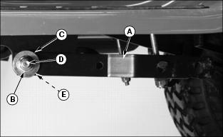
1. Locate draft arms (A) under left and right tractor foot rests. Remove locknut (B), washer (C), and pivot bolt (D) from each side. Discard original pivot bolts.
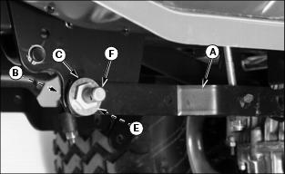
2. Place draft arms (A) back in their original positions. Make sure spacers (E) are installed properly inside draft arms (A).
3. Install original washers (C) on tiller mounting pins (F), from bag of parts, then install in draft arms, spacers, and mounting brackets. Fasten with original locknuts (B) on inside of mounting brackets. Tighten locknuts to 140 N·m (103 lb-ft).
Install Clips On Tiller Frame Rails
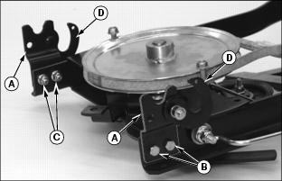
From bag of parts, install left and right tiller clips (A) to outside of correct tiller frame rails, so latches (D) flip forward. Fasten with two M8 x 1.25 x 25 mm hex bolts (B) and M8 x 1.25 locknuts (C). Tighten locknuts to 28 N·m (247 lb-in.).
Put Tiller Frame Rails In Transport Position
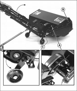
1. Pull left frame rail up until locking pin (A) can be locked into locking bracket hole. Push down on tiller handle (B) to rotate tiller housing while pulling left frame rail up to gain clearance to lower left frame wheel.
2. Unlock locking pin (C) and rotate wheel down into engaged position and make sure locking pin locks in locking hole. Lock right frame wheel down into engaged position in similar fashion.
Install Lift Handle And Idler Sheave
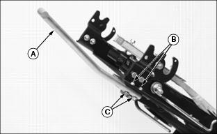
1. From bag of parts, install lift handle (A) under left frame rail with two M6 x 1.0 x 30 mm flange bolts (B), top-down, and fasten with two M6 x 1.0 flange nuts (C). Tighten two flange nuts to 17 N·m (150 lb-in.).
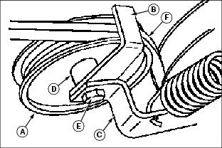
2. From bag of parts, position idler sheave (A) and belt guide (B) onto tiller tensioning arm (C). Make sure shoulder (D) on sheave is seated against the belt guide.
3. Install M8 x 1.25 x 50 mm flange bolt (E) from bottom side of tensioning arm. Install M8 x 1.25 locknut on top side of sheave finger tight only.
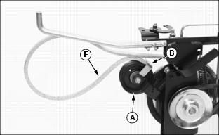
4. Remove shipping tape from belt and route belt between belt guide (B) and idler sheave (A) so small V-edge (F) is facing belt guide.
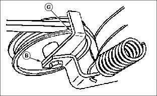
5. Adjust the position of belt guide (B) as shown. Make sure belt guide does not contact idler sheave at (G).
NOTE: Make sure belt guide does not move out of position when tightening locknut.
6. Tighten M8 x 1.25 locknut to 40 N·m (354 lb-in.).
7. After tightening, make sure the idler sheave rotates freely on the tensioning arm.
8. Pull the belt tight and make sure belt guide does not contact idler sheave or belt.
Adjust Tiller Lift Rod
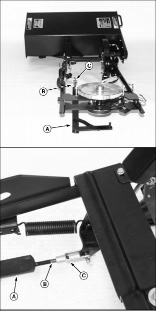
Turn threaded end (B) of tiller lift rod (A) clockwise into clevis (C), far enough so three-to-four threads are exposed inside clevis.