
Installing
Park Vehicle Safely
· Stop vehicle on a level surface, not on a slope.
· Before you leave the operator's seat, wait for engine and all moving parts to STOP.
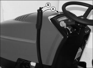
Setting Depth Control Knob
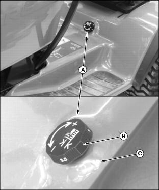
Turn depth control knob (A) to "ZERO" setting (B), raised indicator that is blank should be aligned with fender deck raised indicator (C).
Move Implement Lift Lever
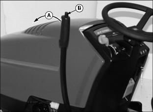
1. Pull implement lift lever (A) rearward slightly, then depress and hold down button (B) to unlock lift lever locking mechanism.
2. Push lift lever (A) forward out of "RAISE" position, release button (B) as you continue to push lift lever all-the-way forward until a loud metallic-click is heard, signalling lever is in "LOCK-OUT" position, then release lift lever-it is now locked into "LOWER" position.
Put Tiller Frame Rails In Transport Position
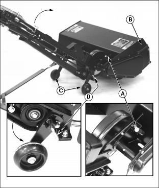
1. Pull left frame rail up until locking pin (A) can be locked into locking bracket hole. Push down on tiller housing handle (B) to rotate tiller housing while pulling left frame rail upwards to gain clearance to lower frame wheels (C).
2. Unlock locking pin (D) and rotate frame wheel down into engaged position and make sure locking pin locks into locking hole. Lock right frame wheel down into engaged position in similar fashion.
Install Tiller On Tractor Rear-Frame Mounting Hardware
1. Roll tiller under rear of tractor.
2. Get a helper or use a floor jack with wheels to safely lift and install tiller, frame hooks (A) slide over spacers (B) of rear-frame mounting hardware.
Engage Frame Support Rod
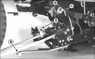
1. Move to left side, under tractor footrest-open tiller latch clips (A) at both sides of tiller.
2. Push and hold down lift handle (B).
3. Pivot left-side frame support rod (C) upward so loop in rod is under mounting pin (D) of tractor frame.
4. Slowly release downward pressure on lift handle (B) to engage rod loop.
Lock Frame Wheels into Storage Position

1. Move to left rear, behind tractor drive wheels-pull and hold out wheel locking pin (A).
2. Swing left wheel assembly (B) up into "RAISED" position. Make sure locking pin engages hole in locking bracket. Repeat steps for right frame wheel.
Disengage Frame Support Rod
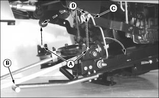
1. Move to left side, under tractor footrest-hold lift handle (B) down.
2. Pivot support rod (C) down into storage position.
3. Slowly release downward pressure on lift handle (B) until cups of tiller frame latches (A) are seated up against mounting pins (D).
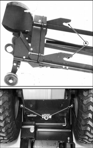
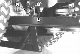
Fasten Frame Clip Latches And Install Belt
1. Close clip of latch (A) around mounting pin (B) on each side of tractor.
2. Install spring locking pin (C), from bag of parts, into holes of each clip latch (A), outside-in, to prevent clips from vibrating or bouncing open.
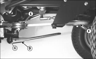
3. Move to right side, under tractor footrest-swing belt tensioning lever (D) toward front of tractor to loosen belt tensioning idler (E).
4. Move belt tensioning idler (E), by hand, towards right frame to help install belt on PTO drive sheave (F). Release idler after belt is completely seated in sheave.
5. Swing belt tensioning lever (D) toward rear of tractor to tighten belt.
Fasten Tiller Lift Rod to Tractor Lift Link
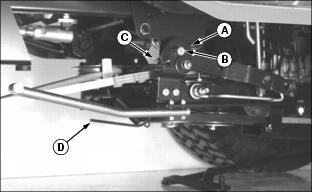
NOTE: Lock implement lift lever into "LOWER" position and unlock tiller housing from "TRANSPORT" position and lower it onto ground before fastening tiller lift rod (B)-this allows ease-of-alignment between tractor lift link (A) and tiller lift rod pin (C).
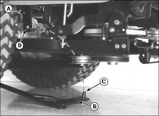
1. Move to right side, under tractor footrest-as you rotate tiller lift rod (B) upright, align tractor lift link (A) so pin (C) fits into hole (D) of lift link (A).
2. Install M13 x 24 x 2.5 mm washer (E), from bag of parts, on lift rod pin (C).
3. Fasten lift rod to lift link with spring locking ring (F), from bag of parts.
Adjust Tiller Lift Height
1. Push implement lift lever (A) forward slightly, then depress and hold down button (B) to unlock lift lever locking mechanism.
2. Pull lift lever (A) reward out of "LOWER" position, release button (B) and continue to pull lever all-the-way reward until a loud metallic-click is heard, signalling lever is in "LOCK-OUT" position, then release lift lever-it is now locked into "RAISE" position.
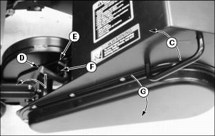
3. Move to left side of tiller housing-grasp handle (C) to raise tiller housing to remove pressure on transport locking pin (D) and continue to hold tiller housing stationary while you pull transport locking pin (D) out and rotate it forward into "LOCK-OUT" position, rolled pin (E) locked in frame slot (F).
4. Slowly lower tiller housing down (G) against tractor lift linkage.
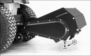
5. Measure distance (C) between lowest tine and ground. Distance should be 75 mm (3-in.). This will allow a maximum 150 mm (6-in.) tilling depth and enough ground clearance for turns on ends of tilling area. If distance is not correct, see Adjusting Tilling Depth in the OPERATING section.