
Operating
Tilling Tips
Install correct front and rear tractor weights. See Install Weights and Chains in Installing the Tiller section.
Till with engine at FAST throttle, control ground speed with appropriate transmission speed range.
Check tines before you till. Replace missing, bent, or broken tines.
When you till hard ground or sod, till at a shallow depth for the first pass. Till deeper on each pass after that.
When you till a small area, make a pass through the middle, then circle alongside the original pass, working to the outside. After you finish, make a few passes around the edge to cover ridges left by turning.
Till straight ahead when possible. This will leave fewer ridges from turning.
For seed bed preparation, till the soil once in the fall. Decaying vegetation will add valuable nutrients to the soil by spring. If the terrain is hilly or uneven, wait until spring, or leave some untilled strips, to help reduce soil erosion. The climate and terrain will help you decide the best time to till.
Before Tilling

Test soil condition by squeezing it in your hand. If soil forms a ball, it is too wet to till. If soil does not compress easily or falls apart, it is ready to till.
DO NOT till when soil is wet. Wet soil will stick to tines and tine shaft. Wet soil will clump-up and dry out hard, making it difficult to work during the growing season.
Before tilling mow tall weeds and grass to keep them from wrapping around tines or tine shaft.
Always pick up rocks, branches, and other objects that might damage tiller.
Always check tines before tilling. Repair or replace loose, bent, or broken tines.
Move Implement to "LOWER" Position
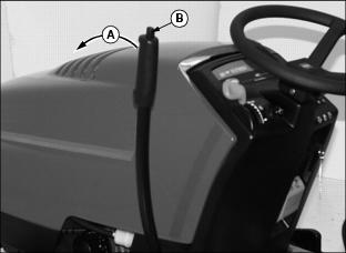
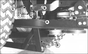
1. First pull implement lift lever (A) rearward slightly, then depress and hold down button (B) to unlock lift lever locking mechanism.
2. Push lift lever (A) forward out of "RAISE" position (shown), release button (B) as you continue to push lift lever all-the-way forward until a loud metallic-click is heard, signalling lever is in "LOCK-OUT" position, then release lift lever-it is now locked into "LOWER" position (see next figure).
"LOCK-OUT" Position: locks tiller in "LOWER" position-for difficult conditions, such as, heavy soils, clay, or sod. When lift lever is "LOCKED-OUT" this means the lift spring in the lift linkage has no effect on tiller weight.
Move Implement to "RAISE" Position

1. First push implement lift lever (A) forward slightly, then depress and hold down button (B) to unlock lift lever locking mechanism.
2. Pull lift lever reward out of "LOWER" position, release button (B) and continue to pull lever all-the-way reward until a loud metallic-click is heard, signalling lever is in "LOCK-OUT" position, then release lift lever-it is now locked into "RAISE" position.
"LOCK-OUT" Position: locks tiller in "RAISE" position-for making turns at end of rows. When lift lever is "LOCKED-OUT" this means the lift spring in the lift linkage has no effect on tiller weight.
Move Implement to "FLOAT" Position
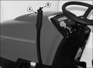
1. First pull implement lift lever (A) rearward slightly, then depress and hold down button (B) to unlock lift lever locking mechanism.
2. Push lift lever (A) out of "RAISE" position, release button (B) and lift lever. Lift lever is now in "FLOAT" position (between "RAISE" and "LOWER" positions).
"FLOAT" Position allows implement to move with contour of ground which causes the lift spring in the lift linkage to exert maximum depth force on tiller weight. "FLOAT" position performs best in light-to-medium soils: such as sandy, loam, or soils previously tilled.
Using Depth Control Knob
Adjust depth control knob to set tilling depth. Tiller will return to the same depth each time you lower it.
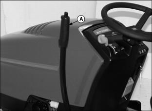
1. Use lift lever (B) to raise tiller as high as it will go.
2. Turn knob (A) clockwise to raise the tiller depth or counter-clockwise to lower the depth, as viewed from operator's seat.
3. If you cannot adjust for the desired tilling depth, see Adjusting Tilling Depth.
Adjusting Tilling Depth
1. Stop engine and set PARK brake.
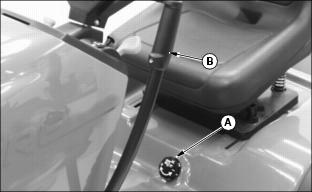
2. "LOCK-OUT" lift lever (A) into "LOWER" position to release spring tension in lift linkage.
3. Move to right side, below tractor footrest-remove spring locking ring (A) and flat washer (B) form lift rod pin (C).
4. Remove lift rod (D) form tractor lift link (E).
|
DO NOT expose more than 30 mm (1-1/4 in.) of thread (G) or lift rod and clevis threads could be damaged or lift rod could separate from clevis. |
NOTE: Maximum tilling depth is 150 mm (6-in.)-bottom of shaft to bottom edge of lowest tine.
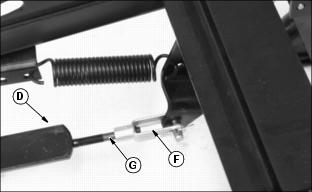
Picture Note: Tiller frame removed from tractor for clarity.
5. Turn lift rod (D) clockwise into clevis (F) to increase tilling depth and counterclockwise out of clevis (F) to decrease tilling depth.
6. Fasten lift rod (D) to tractor lift link (E) with washer (B) and spring locking ring (A).
7. Check tiller ground clearance:
· Use lift lever to raise tiller as high as it will go.
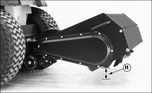
· Measure distance (H) between ground and the lowest tine. The distance should be 75 mm (3-in.).
Operating Tiller
· Pick up objects from tilling area. · Guards and shields must be in place. · Clear the work area of people. |

1. Move to rear of tractor-lock frame wheels (A) in the RAISED position (shown). Make sure locking pins (B) are locked into locking bracket hole.
2. Move to left side of tiller housing-grasp handle (C) to raise tiller housing to remove pressure on transport locking pin (D) and continue to hold tiller housing stationary while you pull transport locking pin (D) out and rotate it forward into "LOCK-OUT" position, rolled pin (E) locked in frame slot (F).
3. Slowly lower tiller housing down (G) against tractor lift linkage.
4. Start engine. Put throttle lever at 1/4 position. (See your tractor operator's manual for throttle lever operation.)
NOTE: For those tractors with Reverse Implement Option (RIO), the tiller will stop when the tractor is put in reverse unless Reverse Implement Switch (RIS) is activated before going in reverse.
5. To engage tiller, put PTO control in the ON position. (See your tractor operator's manual for PTO operation.)
6. Push throttle lever to the FAST position.
8. Till ground at a safe travel speed using appropriate transmission ground speed.
Inspecting Or Unplugging Tiller
2. Put PTO control in the OFF position.
3. Lower tiller to the ground.

7. Move to rear of tiller-lift shield (A) to gain access to tines and shaft.
8. Safely inspect or unplug tines and shaft area.
Parking Tiller
1. STOP tractor and turn PTO switch OFF.
2. STOP engine, LOCK park brake, and remove key.
Transporting Tiller
Drive the tractor with the tiller in the "TRANSPORT" position when traveling from one tilling area to the other. Drive the tractor at a safe travel speed. Slow down on slopes or rough ground.
Place tiller in "TRANSPORT" position as follows:

1. First push implement lift lever (A) forward slightly, then depress and hold down button (B) to unlock lift lever locking mechanism.
2. Pull lift lever (A) reward out of "LOWER" position (shown), release button (B) and continue to pull lever all-the-way reward until a loud metallic-click is heard, signalling lever is in "LOCK-OUT" position, then release lift lever-it is now locked into "RAISE" position, lift lever in close proximity to steering wheel.
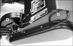
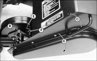
3. Move to left side of tiller housing-grasp handle (C) to raise tiller housing to align transport locking pin (D) and transport bracket locking hole (E). Rotate transport locking pin (D) reward to unlock rolled pin (F) from frame slot (G) and release transport locking pin so it springs into "LOCK-OUT" position in transport bracket locking hole (E).
4. Slowly lift up and push down on handle (C) before releasing it to ensure tiller housing is "LOCKED-OUT" into "TRANSPORT" position.