
Service
Service Intervals
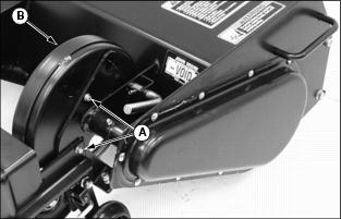
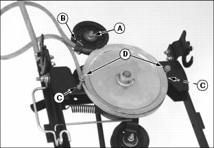
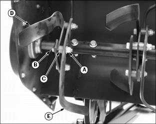
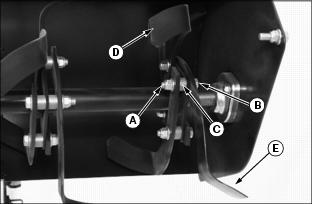
Checking Belt Tension
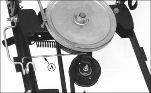
Picture Note: Tiller removed for clarity purposes only.
1. Check position of belt tension rod (A):
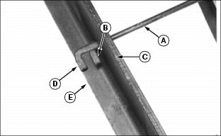
· If rod end is in position (B), against the vertical frame rail (C), the belt is too tight and must be loosened.
· If rod end is in position (D), extends beyond horizontal frame rail (E), the belt is too loose and must be tightened.
· Move to left rear of tiller frame-loosen nut (F) on the idler pulley.
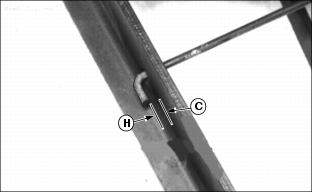
· To tighten belt-turn bolt (G) counter-clockwise until a 3 mm (1/8 in.) clearance exists between inside edge of rod end (H) and vertical frame rail (C).
· To loosen belt-turn bolt (G) clockwise until a 3mm (1/8 in.) clearance exists between inside edge of rod end (H) and vertical frame rail (C).
· Tighten nut (F) on the idler pulley after adjustment.
Cleaning Under Belt Shield
Picture Note: Tiller removed for clarity purposes only.
1. Move to left side of tiller housing-remove two self-tapping cap screws (A) and belt shield (B).
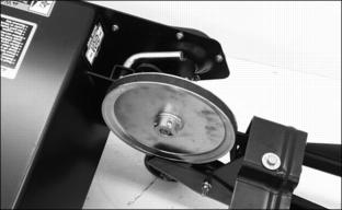
2. Clean dirt from sheave and surrounding area.
3. Install shield (B) and self-tapping cap screws (A) until snug-DO NOT over-tighten or you may damage threads in shield holes.
Lubricating Drive Sheave Bearing
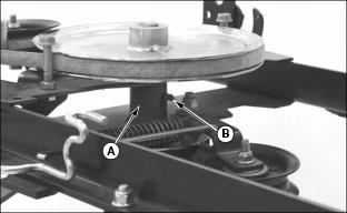
Picture Note: Tiller removed for clarity purposes only.
Move to front of tiller frame-lubricate drive shaft assembly bearing (A) at grease fitting (B) with a Multi-Purpose Grease, or equivalent, until grease comes out of bearing seals.
Lubricating Rear Jackshaft
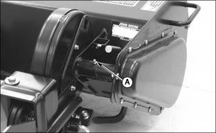
Picture Note: Tiller removed for clarity purposes only.
Move to left side of tiller housing-lubricate jackshaft grease fitting (A) with two or three shots of a Multi-Purpose Grease, or equivalent.
Remove Primary Drive Belt
1. Remove tiller from tractor. (See the REMOVING section.)
2. Loosen flange lock nut (A) on tensioning idler. Move belt guide (B) away from belt.
3. Loosen top jam nuts (C), one on each side, to tilt guide bolts (D) away from drive sheave.
Install Primary Drive Belt
1. Install belt on drive sheave with wide-edge of belt facing guide bolts (D).
2. Tighten top jam nuts (C), one on each side, to properly align guide bolts (D).
3. Install belt between tensioning idler and belt guide (B) so narrow-edge of belt faces belt guide (B).
4. Position belt guide (B), as shown. Tighten tensioning idler flange lock nut (A) to 40 N·m (354 lb-in.) while holding belt guide stationary.
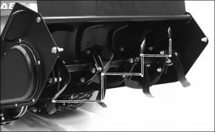
Remove Secondary Drive Belt
1. Remove tiller from tractor. (See the REMOVING section.)
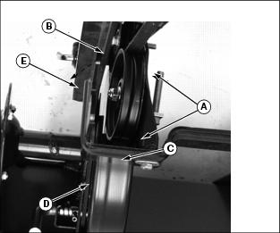
2. Remove two self-tapping cap screws (A) to remove belt shield (B).
3. Loosen flange nut (C) to loosen tensioning idler (D).
4. Turn bolt (E) clockwise to move tensioning idler (D) up in the slot.

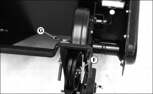
5. Move to front of tiller frame-remove secondary belt from front idler (F) and front drive sheave (G).
6. Move to left rear of tiller-remove lock nut (H) on inside of frame from idler mounting bolt (I) to remove V-idler (J) from inside of belt.
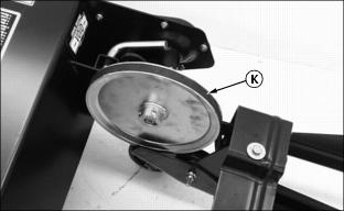
7. Remove secondary belt (K) from tiller drive sheave.
Install Secondary Drive Belt
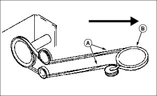
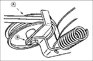
1. Install new secondary drive belt with one twist (A), as shown, to seat "V" of belt in secondary drive sheave (B). DO NOT cross-over belt (forming an "X" pattern) when installing or tiller drive rotation will be reversed.
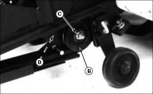
2. Move to left rear of tiller-install V-idler (B) inside belt and fasten with mounting bolt (C), outside-in, and tighten with lock nut (D) on inside of frame.
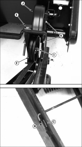
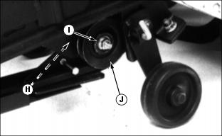
3. Turn bolt (E) counterclockwise to move tensioning idler (F) as far down in slot as necessary to tension belt properly-until inside-edge of front gauge rod (G) has 3 mm (1/8 in.) clearance from vertical frame rail (H).
4. Tighten tensioning idler nut (I).
5. Install shield (J) and fasten with two self tapping cap screws (K) until snug-DO NOT over-tighten or you may damage threads in shield holes.
Replacing Tines
2. Raise tiller as high as it will go if still on tractor.
NOTE: For ease in replacing tines, you can remove tiller from the tractor and turn it completely upside down. Put down protective tarp or carpet to protect paint finish.
3. Put tiller in TRANSPORT position. (See Transporting Tiller in OPERATING section.)
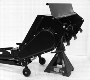
4. Safely put jack stand or blocks under tiller (tiller removed or still on tractor).
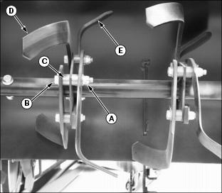
NOTE: Make sure you install the new tines and hardware EXACTLY as the old tines and hardware were positioned. Use the pictures to help you install tines correctly. Properly installed tines have a step-up pattern from left-to-right.
Each cluster of tines MUST have two left tines (D) and two right tines (E):
· Alternate left and right tines in each cluster.
· A bolt with NO SPACER is an M10 x 35 bolt.
· A bolt with ONE SPACER is an M10 x 45 bolt.
· A bolt with TWO SPACERS is an M10 x 60 bolt.
6. Tighten all lock nuts to 75 N·m (55 lb-ft).
Replacing Shaft Bolts
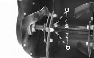
1. Move to left side of tiller shaft-remove lock nuts (A) and bolts (B).
2. Align shaft holes and install new bolts (B) and lock nuts (A). Tighten lock nuts to 75 N·m (55 lb-ft).
Grease
Use a SAE Multi-purpose grease based on the expected air temperature range during the service interval.