
Assembly
Remove from Crate
Parts in Bag
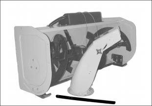
1. Remove attachment and hydraulic hose assembly, discharge chute, drift blade and bag of parts.
3. See your Front Hitch Kit Installation Instructions for assembling the following hardware:
• Large Spring Locking Pin (Used with Front Hitch Kit)
• Tether Assembly (Used with Front Hitch Kit)
The above parts are used to restrict the hitch from angling with the attachment.
Identify Drive Assembly Parts

Parts in Box
Parts in Bag
Install Discharge Chute
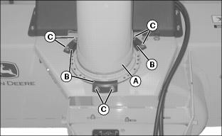
1. Put light coat of John Deere Moly High Temperature EP Grease or an equivalent onto discharge chute base and install discharge chute (A).
2. Install three large clips (B), and fasten with six self tapping flange head bolts (C).
3. Tighten bolts. Chute should rotate freely after tightening.
Install Discharge Chute Cables

1. Lay cables (A) over attachment shell.
IMPORTANT: Avoid damage! Hydraulic cylinder plunger must be in the retracted position (all the way in the cylinder) when beginning this procedure. |
2. Remove cable shield (B) and verify that chute cables are still on pulleys.
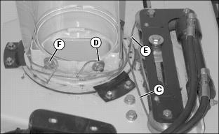
4. Stand behind attachment. Take right cable (C) and wrap around chute counterclockwise.
5. Use locking pliers and pull cable tight around threaded stud, and behind lock nut and washer (D).
7. Wrap left cable (E) around chute clockwise.
8. Use locking pliers and pull cable tight around threaded stud, and behind lock nut and washer (F).
10. Tuck excess ends of cables under cable.
IMPORTANT: Avoid damage! Make sure you install the long bolts through the black cable shield and bracket. |
11. Install black cable shield and bracket with four bolts and lock nuts.
Lubricating Driveshaft

• Lubricate driveshaft grease fittings (A) with John Deere Moly High Temperature EP Grease or an equivalent.
Install Driveshaft

1. Install woodruff key (A) in gearbox shaft groove.
2. Apply John Deere NEVER SEEZ® lubricant or an equivalent on sprocket shaft (B).
3. Align groove in driveshaft with key on sprocket shaft and push driveshaft on sprocket shaft.
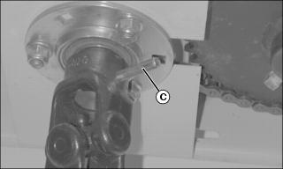
4. Align holes on sprocket shaft with holes in driveshaft and install rolled pin (C) through both shafts.
5. Install plastic coated retainer wire through rolled pin and twist both ends of wire together a minimum of three turns.
Lubricating Auger Shaft
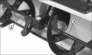
• Lubricate grease fittings (A) with John Deere Moly High Temperature EP Grease or an equivalent.
Install Upstop
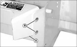
1. Install upstop (A) on attachment and fasten with four M8x25 carriage bolts (B) and M8 nuts, two on each side.
Install Tie Strap
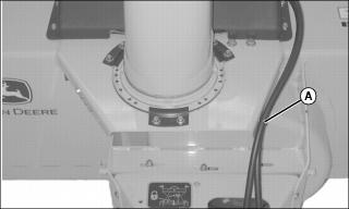
1. Insert tie strap (A) through hole on right side of attachment.
2. Fasten hydraulic hoses to attachment housing with tie strap.
Install Driveshaft Support Rod
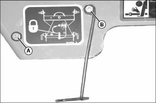
1. Install an M8x25 hex bolt (A) and into the hole on the left side of the upstop and secure with an M8 nut.
2. Install an M8x25 hex bolt (B) through the support rod hole, the washer from the kit, and through the hole on the right side of the upstop. Secure with an M8 locknut.
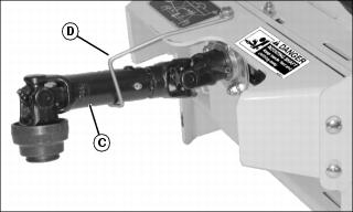
3. Install driveshaft (C) on end of support rod (D).
Install Drift Blade
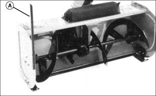
1. Install drift blade (A) with two M6x25 hex head bolts and M6 lock nuts to the right side of the attachment housing.