
Installing
Preparing the Vehicle
NOTE: Read and complete the Assembly section at the back of this operator manual if installing the attachment for the first time.
Required Equipment
Machine Setup
Check tire pressure of machine before operating machine.
Installing Chains or Ballast
When the attachment is removed, also remove any ballast that was added to the machine. Use only attachments and accessories recommended by the manufacturer. |
NOTE: Certain working conditions may be improved by using tire chains or ballast.
To Improve Traction
• Install chains on rear drive tires
• Install liquid ballast in drive tires
• Install wheel weights on rear drive wheels
• Install rear suitcase weights with rear weight bracket
• Install ballast box and weight, frame mounted or mounted to 3-point hitch kit
Installing Attachment to Front Hitch
IMPORTANT: Avoid damage! To prevent damage to driveshaft: • Do not angle snow removal attachment. • Put attachment driveshaft on support rod before driving machine forward. |
1. Park machine safely. (See Parking Safely in the SAFETY section.)
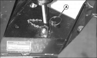
2. Insert locking pin assembly (A) in front hole on front hitch and fasten with spring locking pin.
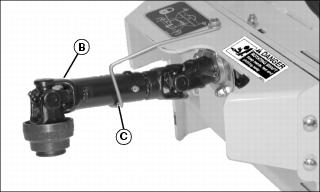
3. Install driveshaft (B) on support rod (C).
NOTE: Locking pin lever (D) on each side of front hitch bracket must be in the unlocked position shown.
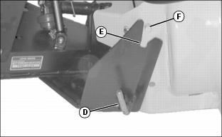
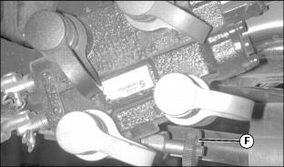
5. Move machine forward slowly until slot (E) on front hitch bracket lines up with pin (F) on attachment.
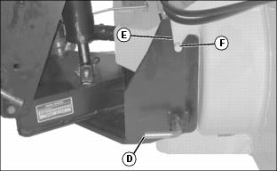
6. Raise front hitch until slot (E) locks in place under pin (F) and locking pins (D) click into hitch bracket.
7. Lower attachment to the ground.
8. Install hose locking ring to right side of front hitch.
• Locking ring can remain installed when the attachment is removed.
Connecting Driveshaft
1. Park machine safely. (See Parking Safely in the SAFETY section.)
2. Remove attachment driveshaft from support rod.

3. Pull back coupler (A) on driveshaft to lock collar open.
4. Push driveshaft onto PTO shaft until coupler (A) locks into place.
Connecting Hydraulic Hoses
1. Move hydraulic control levers back and forth to relieve hydraulic pressure.
2. If machine is equipped with angling kit, disconnect the angling kit hoses from machine hydraulic ports. Fasten the unused angling kit hoses to the existing hydraulic hoses using wire ties so they do not drag on the ground, or remove Angling Kit completely.
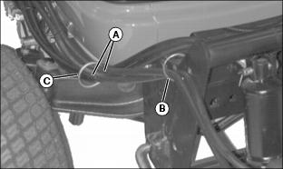
3. Route hydraulic chute hoses (A) through ring (B) on hitch bracket, through hose bracket (C) and then connect to hydraulic outlet on machine.
4. Match color on hose with color on machine port and install attachment hoses in ports. (See decal on machine platform.)
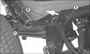
5. Route hydraulic lift hoses (D) on the inside of hitch bracket (E) and then through hose bracket (C) as shown by arrows, to eliminate pinching of hoses when lifting attachment.
6. Turn lift dial on mower to 5 to bring the mower and 3-point hitch to full-lift position.
7. If machine is equipped with lockout valve (F), turn valve clockwise until closed to lockout mower and rear hydraulic implement lift.
Checking Hydraulic Hoses and Fluid Level
1. Remove transaxle hydraulic fluid dip stick.
2. Check fluid level. Add fluid if necessary.
5. Move hydraulic control levers back and forth to check for leaks.
Checking Discharge Chute Rotation
NOTE: If chute does not move in the direction indicated, reverse hose location in ports.
2. Turn chute in both directions:
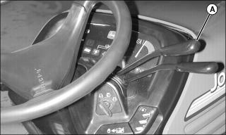
• Pull lever (A) back to rotate chute to the right.
• Push lever (A) forward to rotate chute to the left.
IMPORTANT: Avoid damage! Ensure proper rotation of chute. Position chute to face right (as viewed from seat) before adjusting cables. |
