
Assembly
Identify Parts
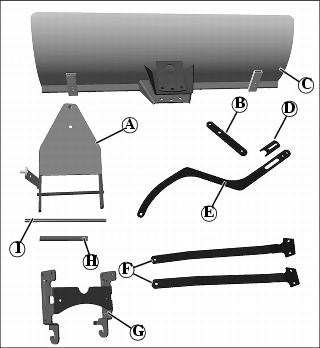
B - Bracket, Foot Lift (In bag of parts)
D - Adjusting Bracket (In bag of parts)
Bag of Parts:
Preparing Vehicle
1. Install spring bracket on foot lift plate.
NOTE: The spring bracket may already be installed if your machine is equipped with the lift assist spring and can remain on the machine when the blade is removed.
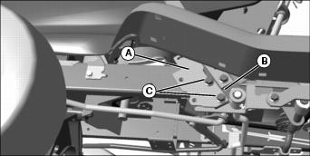
Picture Note: Foot lift is located on left side.
2. Align two right holes in spring bracket (A) with holes in foot lift latch plate (B) and fasten with two M10x25 bolts (C) and M10 locknuts.
Install Skid Shoes
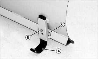
• Install each skid shoe (A) with small drilled pin (B) and small spring locking pin (C).
Fasten Support Bars to Lift Assembly
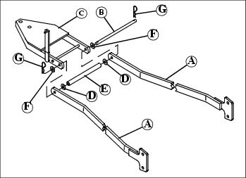
1. Position support bars (A) as shown. Slide draft pin (B) through one side of blade lift arm (C) and one support bar (A).
2. Slide one 17/32x1.25x0.060 washer (D) onto the draft pin.
3. Slide blade spacer (E) onto the draft pin.
4. Slide one 17/32x1.25x0.060 washer (D) onto the draft pin.
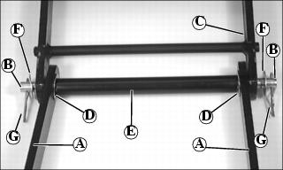
5. Slide draft pin through other support brace and out the other side of the blade lift arm.
6. Slide one 17/32x1.25x0.060 washer (F) onto each side of the draft pin.
7. Install a small spring locking pin (G) completely through the holes on each end of the draft arm.
Assemble Lift Brackets
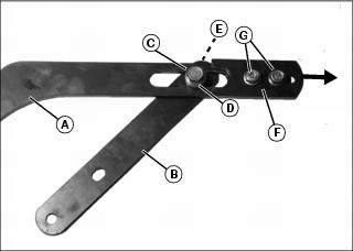
1. Attach lift bar (A) to foot lift bracket (B) with M10x35 bolt (C) and shoulder bushing (D). Be sure shoulder of bushing is under bolt head as shown. Secure with M10 locknut (E).
2. Attach adjustment bracket (F) with two M8x25 bolts (G) and M8 nuts. Slide bracket (F) out to furthest position from slot in lift bar and tighten hardware.