
Installing the Attachment
Installing Tractor Weights and Chains
Use recommended rear weights to improve stability when operating with blade. |
NOTE: Before attaching blade, remove mower deck from tractor. (See Tractor Operator’s Manual.)
See your John Deere dealer for weights and chains.
To help traction in difficult conditions it is recommended you:
• Install rear wheel weights on tractor.
• Install chains on rear tractor tires.
Checking Tire Pressure
IMPORTANT: Avoid damage! To prevent damage to tire: Do not use more than maximum tire pressure shown on sidewall of tire. |
Inflate tires to correct pressure:
Installing Lift Assembly to Tractor Frame
1. Park machine safely. (See Parking Safely in the SAFETY section.)
NOTE: If installing the blade for the first time, follow step 4. If not, continue with step 5. The support bracket and pivot bolts do not have to be removed when installing the mower deck.
4. Install support bracket to tractor frame and pivot bolts to draft arms.
Remove Hood
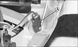
b. Disconnect headlight electrical connector (A) located near the right front pivot.
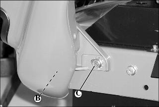
c. Loosen two cap screws (B), one on each side, supporting hood and front bumper to tractor frame.
d. Support the hood and remove two cap screws, one on each side, and external tooth lock washers (C).
e. Remove hood and bumper from the tractor as an assembly.
Remove Muffler Shields
NOTE: Appearance of muffler shields may differ based on model selected within tractor series.
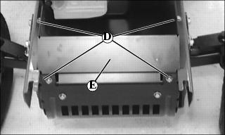
a. Remove four cap screws (D) and muffler shield (E).
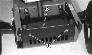
b. Remove two cap screws (F) and lower muffler shield (G).
Install Blade Support Bracket
NOTE: Retain hardware and install in each side of tractor frame if removal of blade support bracket is desired.
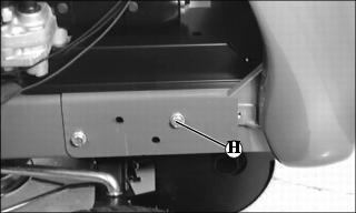
a. Remove existing bolt (H) and nut from each side of tractor frame.
Picture Note: Bolts are installed to the outside.
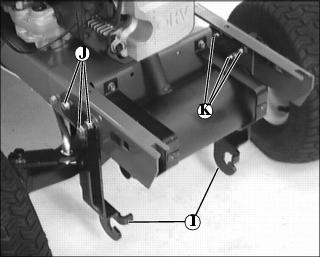
b. Install blade support bracket (I) to tractor frame with six bolts (J) to the outside and locknuts (K). Make sure J-hooked ends on support bracket face forward.
Install Pivot Bolts
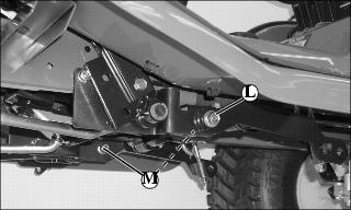
a. Remove nut (L) and bolt (M) from front of draft arm under each side of tractor. Keep bushing in draft arm.
NOTE: Pivot pin studs must face inside tractor frame. Threaded end of each pivot pin with attaching nut must face to the outside of tractor frame.
Use nuts (L) removed from each draft arm when installing pivot pins. Retain bolts (M) and install in tractor frame if removal of pivot pins is desired.
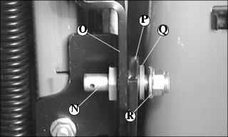
b. Install pivot pin (N), one on each side, through bracket (O), draft arm (P) and bushing (Q).
c. Install nut (R), one on each side.
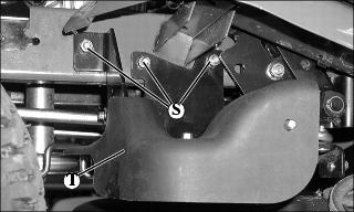
5. On LTR180: Remove three bolts (S) and drive belt idler assembly bracket and shield (T).
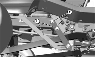
6. Install lift bracket assembly (U) on spring bracket and secure with two M10x30 bolts (V) and M10 locknuts.
7. Slide lift assembly under tractor.
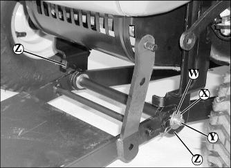
8. Move washer (W) close to spring locking pin (X) on each end of front draft pin (Y).
9. Install front draft pin into each J-hook on each side of tractor mounted blade support bracket (Z).
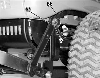
10. Lift front of blade lift assembly and push lift pedal back towards rear of tractor to align pin in bracket (aa) with hole in lift bracket (bb) and secure with 10.5x30x2.5 mm washer and locking ring (cc).
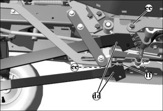
11. Use upper hole in support bars (dd) and install bars to pivot pins (ee) and secure with spring locking pins (ff).
NOTE: If installing the blade for the first time, make sure the blade lift assembly fits properly before installing the muffler shield and hood and follow the next steps. If not, continue with Installing Blade to Lift Assembly.
12. Check that the blade lift assembly and support bars fit properly.
13. Tighten six nuts on blade support bracket.
14. Tighten nuts on pivot pins.
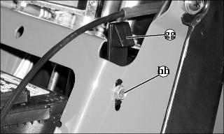
• Make sure tabs on hood are seated properly in holes in foot rest and that hood latches properly. Adjust height of hood latch (gg), one on each side, if necessary. Tighten cap screws (hh).
Installing Blade to Lift Assembly
1. Push lift pedal down and lock in the transport position.
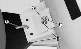
2. Attach blade to lift assembly with large drilled pin (A), 0.656x1.0x0.060 in. washer (B) and large spring locking pin (C).